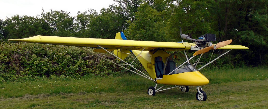
Exciting developments

The first thing I did today was nip across to Damyn’s Hall Airfield just over the Thames in Essex to meet Ian and pick up the Arplast from him. Ian is a microlight instructor there and just as I arrived I saw him taking off with a student in a flexwing. This was my first visit to Damyn’s Hall and not the last, I hope, because it’s a smashing little field with two runways, good facilities and a very nice cafe. Despite its being a slightly chilly, blustery day, there were quite a few members of the public with their kids watching what was going on, going off for helicopter rides and generally enjoying themselves. That’s what General Aviation should be like in this country but Damyn’s, like many other small airfields across the country, is under the usual planning threats. Let’s hope that the killjoys don’t succeed in their aims 😕

After a couple of circuits Ian stopped briefly to dig out the prop hub (Ian’s wife and I had already found the blades) and having done so we did the deal quickly so Ian could get back into the air. With this weather he needs to get all the hours in he can. I think I’ll have to give him a call later on and see if he’s got any paperwork for the prop because I think I’ll need some to fit it as a Mod to MYRO. After I got home I gave it a quick clean up and although it’s obviously done a few hours, it came up very nicely.

Then I was able to make a start on the next big MYRO job, namely the screen, but first I took a few pics of the work I did yesterday. Yesterday’s main job was routing the cables and the next pics show how I’ve routed them out from under the panel, up the front tube and along the main tube where they will join up with the cables from the engine and the battery.

null

null

null

The black tube that you can see in the pic immediately above connects to the fuel pressure gauge and will eventually connect via a T-piece into the rear carburettor’s fuel line. The transparent tube in the top two pics connects to the airspeed indicator and will eventually connect to the pitot tube on the port wing.

The other important job I did yesterday was add a fuel filter into the fuel line which I ran down as far as the electric fuel pump. The following pics show the detail.

null

null

null

The electric fuel pump is bolted in but I haven’t yet completed the fuel line connection from it to the vacuum fuel pump and will not do until the screen is in and I know just how long the fuel pipe should be.

Lastly, remember the pics I showed a couple of weeks or so ago of the underneath of MZEL?. Well here is a similar pic of MYRO. MZEL has the ties between the fuselage cover and rear of the pod done with parachute cording whereas I used cable ties for MYRO. I think that MYRO’s has ended up being a slightly neater job 😉

null

But the main job today was MYRO’s screen. I have to say that I approached it with some trepidation because I had visions of working with horrible brittle plastic and having cracks and splits appear whenever I handled it and tried to make cuts. I could not have been more wrong. I’m not saying that 1.5mm polycarbonate is a joy to work with but it was far less daunting than I expected. I laid a thick cloth sheet (an old bedspread actually) out on the patio and placed the polycarbonate sheet onto it. The plastic is protected on both sides but it still pays to handle it carefully.

I used the old screen as a template by drawing round it in ball point and then made careful measurements to even the sides up in size. The I placed a sheet of ply underneath, took a wooden straight-edge and scored it with a sharp Stanley knife. In some places where I was particularly enthusiastic I cut through but my aim was to score through roughly half way and then finish the cut with scissors. This method worked beautifully and as my stepson said, it avoided the possibilty of causing little splits or tears that could have been caused by a jigsaw, especially one that was too coarse or a bit worn.

After I’d got the main shape cut I needed to get the precise positions and dimensions for the cutouts for the tubes to go through. The originals were all a bit too large but did at least serve as useful indicators, so having no more use for the old screen I cut two big chunks out of each side to make it less unwieldy and replaced it in MYRO. Then I could see exactly where the adjustments to the cutouts needed to be made and marked them accordingly on the new screen. That was as far as I could go because to make the holes I needed tank cutters of the correct sizes. These will do a good, safe job and avoid any damage to the screen. My stepson who has a set was out so as the evening was already beginning to draw to a close I decided to call it a day and doing the cutting is a job for tomorrow. The main beneficiary of the early close was Toddie who jumped at the chance of an early evening walk. And why shouldn’t he 🙂

Getting there

As I’d hoped, the screen plastic did arrive yesterday so if the weather holds, I’ll be able to make a lot of progress and this will be an excellent week-end. I didn’t get on to the screen today but I did get a lot done, nevertheless. Unfortunately I finished too late to take any pics so they will have to wait until tomorrow.

First job, I routed the cables from the cabin, up the front tube to where the electrical connections will be made up on the main tube. This immediately made the cabin look much tidier and I also cleaned some more muck and grease away that I’d missed originally from under the fuel pump on the pilot’s side of the cabin. It’s surprising the difference little things like that can make. Then I got underneath and secured the rear fuselage cover to the back of the pod. Originally it was done using parachute cord but Mark said that cable ties are just as good if not better nowadays for jobs like that, so that’s what I used. Looked very good and was nice and taught at the end of it.

I also got started on running the fuel system. First I put in an in-line filter just along from the tank and then I routed and secured the fuel line down the back of the passenger seat, across the cabin behind the sets and round to the fuel pump. The fuel system components I bought from Mark included the electric fuel pump and the hand primer bulb. However, there have been some slightly alarming postings on the BMAA forum lately about engine failures as a result of blocked primer bulbs and there have been recommendations that they should be removed. So that’s what I’ve decided to do, especially as I have an electric primer pump anyway. But today I only got as far as fitting the electric pump and connecting it to the lower fuel pump before time ran out.

But I’ve also got one last, excellent bit of news. The final item I need to complete MYRO and make it flyable is a prop. When I last flew MYRO it was fitted with the bog standard two-blade wooden prop. Mark still had the hub and one blade of the three-blade Arplast prop that was fitted to MYME when it had its accident and I dearly wanted to have something like that because as well as being newer and more modern, it’s also more efficient. So you get slightly better performance and/or fuel economy. However, when I checked the cost of acquiring two more new blades, the total cost was well above my budget, so I’d resigned myself to getting hold of a standard wooden one.

But the fantastic news is that I’ve come across another Arplast three-blader at a price I can afford. It was originally fitted to a Rotax 503 like mine on an old Spectrum microlight so I know it is the correct one. I’m absolutely delighted with this development and I’ve arranged to take a trip out tomorrow morning to pick it up.

So now it’s just a matter of putting all the bits I’ve got together and I really am getting there 😀

Dohh…

… in the words of Homer Simpson. Rosie very kindly rang me today to tell me where she bought the plastic sheet that she’d made the last screen from. She told me and then just happened to read out what the invoice said … 1.5mm sheet 1025mm wide and 2050mm long. I said that I couldn’t see how she could have made the screen from that as it’s 2300mm wide. She said, ‘Oh yes you can, you cut it diagonally.’ 😕

What a twerp I am – that hadn’t occurred to me. The screen isn’t an oblong shape – it’s more the shape of an eye with an elongated bottom. I checked by marking out a space the size of a sheet on the lawn and then placing the old screen on it. Loads of room around it if you place it diagonally as Rosie said. What a clever girl! That’s saved me a lot of hassle – I then ordered the plastic I need straight away and who knows, if I’m lucky, it might even arrive tomorrow in time for the long week-end. Then anything could happen because as you’ll see below, things are moving briskly along 😉

After patching the holes in the instrument panel, all I then had to do was mate the top and bottom together. Easier said than done. With the instruments in, the panel is quite heavy and very unwieldy and you need at least two pairs of hands to hold the two parts in the correct position while you drill the bottom part through the holes in the top. I solved the problem by hanging the instrument panel upside down from our clothes dryer so it was more or less in the correct position in the panel top, which was lying also upside down on the patio table beneath. I won’t bore you with the details but it worked OK. I found at the end that one of the old end holes in the panel top had been drilled too close to the edge and had split when I secured the fastener so I had to remove that fastener and also the adjacent one and spring the panel parts far enough apart for me to do a repair using fibreglass cloth and epoxy resin. Annoying, but you begin to get used to these continuous snags – it’s an old aircraft after all. Here’s a pic of the panel on the table after I’d finished.

null

I couldn’t wait to get it into the pod, of course which I did fairly quickly and easily, and here are two more pics showing the final result.

null

null

I was very pleased with the outcome – now it’s beginning to look much more like a microlight again. I also think it’s a huge improvement over what was there as well. It’s only fitted in temporarily as the pod is still suspended on string while there’s no screen. But the panel won’t need to come out again so my next job will be to route and cable-tie all the wiring and tubes. That shouldn’t take too long to do and the next job after that will be fitting the screen. So if the plastic does arrive tomorrow, there’s a very good chance if the weather holds that I might get that done on Bank Holiday Monday. Then things do start to get exciting, because at that stage I can start thinking about fitting the engine 😀

For every nice surprise…

… there’s at least one nasty one. At least that’s how it feels at the moment.

I had a very useful conversation with Ben in the BMAA Tech Office today who I found to be very pleasant and approachable. I’d sent him an email about the TIL107 three socket problem and wanted to ask him about it personally. One of the suggestions I’d received on the BMAA forum from Andy Buchan who knows a lot about these things is to put in a 2-pole switch between the car cigarette lighter socket and one of the DIN sockets so that either could be selected but only one of them could be in use at any time. Ben said that he would have no objection to such an arrangement which as far as he was concerned would then meet the requirements of TIL107 as a Standard Minor Mod so long as they were fused accordingly. However, he said that there was an alternative which was to keep all three sockets working, and which, so long as they were also fused accordingly, would be acceptable as a non-standard Minor Mod. The latter is slightly more expensive to be approved but even though I’ve already sourced a 2-pole switch it’s the one I’m going to go for. Having all three sockets and no future hassles is a much better arrangement and hopefully will mean that I’ll need make no additional connections for example, for a radio 12V supply or a supply for an intercom or other radio interface. Either or both will be plug-in and totally removable, which will also save all sorts of other approval hassles.

So that was the nice surprise. Now what about the nasty ones?

Well, there have been two. The first one, which is quite major and hit me totally out of the blue, came when I measured the sheet size of the polycarbonate that I need to make a new screen. It needs to be at least 2300mm wide. However, the largest standard size 1.5mm thick sheet that you can get in the UK is only 2050mm wide. A larger width is available but only if you order a minimum of 20 sheets, which isn’t acceptable, of course. I’ve put out a couple of feelers and have a friend who works in the plastics industry making some enquiries for me so I’m waiting to see what the outcome will be. I’ve also looked at buying sheet in from the USA where 0.06″ (1.5mm) x 4′ x 8′ is the norm but I’m keeping that on the back burner for now.

The other nasty surprise is more minor. When I came to mate up my new panel (that came from MYME) with the panel top (that came from MYRO) I found that the fastening holes do not match up. I suppose when the AX3s were built the parts were undrilled and the builder just got his electric drill and put the holes in where he wanted, by eye, so they were more or less evenly spaced on each side. I almost called Mark at Galaxy to ask about buying MYME’s panel top but then it occurred to me that if I did that the holes in that would not match the fixing holes that are already drilled in MYRO’s pod. So as they will be almost totally covered by the panel top, I decided to fill the existing holes in the instrument panel and effectively start all over. As I type this I’ve already patched the holes on the back of the panel with fibreglass cloth and epoxy resin and I’m just waiting for it to cure before I fill the holes from the front with fibreglass. Then I’ll have yet more colour matching to do! I’m getting quite good at it now 😉

Very productive few days

Quite a few things have come together over the past three or four days which means that MYRO has really moved along. And one of the good things as far as I’m concerned is that it’s been too windy to fly anyway so I don’t feel as though I’ve missed anything. While I was working outside today a flexwing flew over looking decidedly side-ways in the wind! Hopefully he found somewhere to land that’s a bit more sheltered than where we live.

A week or so ago I started a thread on the BMAA forum asking how I should wire up MYRO’s engine hour meter. It expanded into talking about the wiring in general, which is why I posted my wiring diagrams, and I got some very good advice. Amongst other things, whereas I wasn’t going to add any electrical sockets to the panel because I don’t know what I’ll be needing in the future, the consensus was that I should add some now. The one I especially didn’t want to add is a car cigarette lighter socket but it turns out that that’s actually the one you should have because so many accessories (eg GPS’s) come with a car cigarette lighter plug. So I decided to go for two DIN sockets and a car cigarette lighter socket and the bits arrived on Friday.

I did an extension to the wiring diagram that had them all fused and connected on the switched side of the master switch so in MYRO the master switch really is just that. Nothing will become live unless that switch is turned on. I also placed them in a stack on the right hand lower part of the panel so there’s a nice space to the left where I can position my radio. Originally in MYRO the radio was mounted far too low down for my taste and the old Icom that I was using was far from being the easiest model to use anyway because of its small, hard to read screen and horrible tiny little buttons. Don’t tell Rosie I said so, though 😉

Following a very informative thread on the BMAA forum by Rick Moss about installing the CAA charts in a cheap car satnav I’ve also bought and converted one myself. I’ll talk about it in more detail in another posting but it works brilliantly and my initial experiments indicate that it will mount extremely well right in front of you where you want it using its suction mount on the top of the panel. Another small step forward 🙂

I was a bit disappointed actually with the new panel sockets and fuse holders. The fuse holders were bigger than I expected them to be and not of very high quality. The plastic thread of the first one I fitted almost stripped when I tightened down its metal nut so I was very careful with the other two. When I’d finished, I also ‘locked’ them by adding a few drops of epoxy resin to the threads and to the nuts where they were in contact with the back of the panel. and I did the same to be sure with the other sockets too.

I was also disappointed to find that although the DIN sockets looked very nice with little flip up covers, because theye are designed to mount in a metal fascia, they have no earth tags. This meant that I had to solder my earth connections directly to the bodies of the two sockets which was time consuming and also involved their getting very hot. However, it worked and no harm appears to have been done. If I’d thought maybe I should have soldered the connections to the nuts instead while they were removed, but I didn’t 😕

Here are a couple of pics showing the absolute final, finished panel. The first is a composite showing close-ups of the panel back and front and the second is a general shot of the whole panel.

null

null

The only small point of concern is that since I finished the panel wiring, Andy Buchan with his Inspector’s hat on, said that he thinks the relevant BMAA TIL only allows 2 x power sockets, with fairly low total currents drawn from them. He suggests that I put 3 on the form and see what happens – there is a degree of give and take – but check what current I want each power socket to be able to draw and placard and fuse accordingly. So I’m hoping that the worst I’ll need is a placard saying that only two should be used at any time and the maximum load must not exceed 12 amps (say).

Now what else? Today I removed the starboard main undercarriage hub, repacked the bearings with grease and lubricated the brake mechanism, which was luckily in good working order. I also adjusted both brake cables up. Then I got under MYRO and gave the undercarriage cables, which were very dry, a light coating of grease.

Earlier on before I got ‘dirty’, I finished off the last little bit of painting at the front of the fuselage main tube and the tops of the two tubes that support the engine mounts. This is all extremely good news because it now means that MYRO is ready to have its panel and wiring loom installed.

Like I said, things really are now moving on apace 😀

More panel wiring

Got some excellent advice from Andy Buchan and Andy Anderson on the BMAA forum – we’re very fortunate that blokes like them take the time to offer advice and share their knowledge. As a result I’ll be correcting two errors – switching the positions of the fuel pump fuse and switch and adding a 15A fuse upstream of the master switch – and making a couple of really useful additions to the scheme. These are a common earthing point (I’ll fibreglass a small metal bracket to the back of the panel for a bolt to go through) and a busbar for the +12V supply downstream of the master switch. This will make it very easy to add sockets etc for any new accessories in the future because with an earth and a 12V supply easily accessible it will only be necessary to put in a fuse for the new circuit.

I’ve shown these changes in the diagram below.

null

Now looking as it should do, I think 🙂

Panel wiring

I haven’t been able to do any ‘real’ work on MYRO today but I posted my wiring scheme on the BMAA forum in the hope of getting advice and guidance from people like Dave Smith who are more expert in these things than me. Here’s the diagram I posted.

null

I think everything is OK but we’ll see, hopefully. I just tested the master switch neon and I’m glad to say it worked beautifully, lighting up with a nice red colour as soon as I turned the master switch on. Oh, and yes, it did go off when I turned the switch off 😆

In fact I’ve just returned to add that actually I’ve had a very productive evening after all. Whenever I see insulating tape on an electrical connection I know that it’s covering a bodge and usually the neater the tape, the bigger the bodge it covers 🙂

That hasn’t quite been the case with MYME’s old wiring but there was certainly plenty of tape over the EGT and CHT connections and it covered more than a few bodges. If you don’t have a good quality, well made connection, you can’t expect the gauge it connects to work reliably, not in the long term anyway. So I did a few over the weekend and I knew that there were several more needing attention. And that’s what I got done this evening. One or two were very poor and the connectors themselves actually snapped when I separated them. Luckily the new dual EGT gauge came with a short length of connecting cable with connectors on each end and I was able to use those to do the necessary repairs, by cutting them off close to the connector, soldering the connector to the wire in question and then covering the joint with heat shrink that I’d previously placed on the cut wire.

Lovely job – I’m very pleased with the results 😉

Brakes off

Brake off, actually, but I’ll come back to that in a moment.

I had to make a late start today so I had a fair bit to do in quite a short time. The first thing I wanted to do was finish off the panel. All I had to do was fit the remaining gauges (slip ball, airspeed indicator, altimeter and vertical speed indicator) none of which have any electrical connections, but it wasn’t that straightforward because I wanted to re-use the existing mounting screws all of which were quite serviceable but a bit tatty. I decided to give the screw heads a light wire brushing followed by a coat of Hammerite mixed to match the colour of the panel. Judge for yourself if you think the result was successful.

null

I like it and the slightly annoying thing is that unlike the paint I mixed for the panel repairs, the screw heads have stayed nice and shiny! Why couldn’t the panel paint have done so as well 😕

The next job on the list was to remove the main undercarriage wheels, check the brakes for serviceability and regrease the wheel bearings. I started with the port side and here is a pic of the stub axle with the wheel and brake drum removed.

null

I was glad to see that there is still plenty of meat on the brake shoes but when I checked the mechanism I found that it was seized solid. As you can see in the next pic, the mechanism is very simple. The cable operates a lever which causes the small plate against which the bottoms of both shoes rest, to rotate forcing the bottoms of the shoes apart. The tops rest against a round pivot so by forcing the shoes apart they are pushed into contact with the brake drum. Simples 🙂

null

Trouble was the spindle connecting the operating lever and the rotating plate was seized where it passes through the back plate. Nothing for it – spray on WD40 and work the spindle without causing any damage until it was free. Luckily I was successful and I’m glad to say that I got the brake working again. I also checked the other one, although I haven’t stripped it yet, and I’m pleased to say that that one is free and working properly.

While the wheel was off I took the opportunity to re-pack the bearings with fresh grease. Lucky I did as they obviously hadn’t seen any for years! I was then able to reassemble the hub with all of the work done. It should be a doddle doing the other side (famous last words) and with all of the ‘under-panel’ work then done I’ll be able to look forward to refitting the instrument panel, gauges and wiring. That really will be progress and I’m looking forward to it immensely 😀

Panel fitting

When I last flew MYRO it had a pretty good fit of instruments and gauges including the electric fuel pump, of course, and carburettor heat as well as all the usual items like an altimeter, airspeed gauge, cylinder head and exhaust gas temperature gauges etc. However, when I bought MYRO, the carb heat and fuel pump wiring had been removed to go on MZEL, the complete battery side with accessories and wiring had been removed for the same reason and other bits and pieces were either missing or had had wires cut.

That wasn’t a problem, I knew about those things and they were all part of the deal when I bought MYRO. So that’s why when I bought the engine off Mark at Galaxy we took great care to preserve MYME’s wiring loom as far as possible so I could have that along with MYME’s panel and the instruments and gauges it still contained. It meant in effect that MYME’s wiring, instruments and gauges would become MYRO’s and the only problem was that although I was there when many key items were disconnected, for several (notably engine related equipment and accessories) I hadn’t been. And there’s no such thing as an AX3 wiring diagram!

So I’ve had to find and work things out for myself. This was the ‘inventory’, so to speak.

MYRO’s panel still contained a slip ball, airspeed indicator, altimeter, vertical speed indicator, RPM gauge and a dual CHT gauge, still connected. It also had the starter switch still in place and connected but no master switch cabling and although the fuel pump wiring had been removed, there was still a useable fuse holder for it. The dual EGT gauge had been removed and the connections for both temperature gauges had been cut at the engine end.

MYME’s panel came with a complete wiring loom except some connections had been broken by handling. There was the odd anomaly – for example, MYME had a fuel pump with a fuse but apparently no switch to operate it! Also, Mark had removed both temperature gauges but their connections were still in place so based on how MYRO’s dual CHT gauge was connected up, it wouldn’t be difficult to drop two replacements in. MYME’s panel contained a fuel pressure gauge, RPM gauge, a slip ball, airspeed indicator, engine hour meter and a master switch with fuse and wiring.

So my problem was to fill MYME’s instrument panel and successfully connect up all the necessary wiring, to go in MYRO. To do so I had had to buy a new dual EGT gauge to match MYRO’s existing dual CHT one and as MYME’s fuel pressure gauge showed signs of a slight but very oily, dirty leakage and was also stuck at just over 0.2 Bar, I thought it better to replace that with a new gauge as well to save possible future problems.

I worked out that MYRO’s master switch as it had been wired apparently only controlled the accessories – the main 12V live lead was connected straight to the starter switch before then jumping over onto the main fuse holder to which the accessories as far as I could see (as most had already been removed) had been connected. This meant that with the master switch off, you could still start the engine, which I did not like one bit even though it would still need the key to do so. The Rotax 503 wiring diagram does not show any form of master switch so I had to devise my own wiring set up. This has the main 12V supply connecting to one side of the master switch and the other side to the main fuse holder. The other side of the main fuse then connects to the starter circuit on the starter switch which then connects to the starter solenoid. So the starter cannot be activated even with the key in unless the master switch is turned on. A connection is also taken from the switched side of the master switch to the fuel pump switch. This in turn then activates the fuel pump via it’s own fuse.

I’m very happy with the results. I don’t have the faintest idea how this part of MYME’s wiring was done – I’m pretty sure it wasn’t exactly as I’ve done it – but hopefully it will all work as I intend without any future problems. I’ve also tidied up a lot of rather poor connections by removing some pretty awful connectors and making soldered joints enclosed in heat shrink sleeve. This considerably improves both appearance and quality and I believe should lead to good future reliability. I still have a bit more to do in that area as well.

As usual, the job started with ‘repairs’. When I stripped MYME’s panel I found that the RPM gauge it contained was a total bodge being held in place by a thick black goo even though there were some screws in place. So it had to be chucked and MYRO’s one used instead. Trouble was MYRO’s RPM gauge didn’t need holes. The same went for the temperature gauges. The ones that had been removed were screw fit whereas mine were not, so the holes that remained needed to be repaired. The fibreglassing bit of the job was a doddle – the problem was colouring the filler used to match the rest of the panel. I didn’t expect to be able to make the holes invisible but I also didn’t want them to stick out too much like a sore thumb. In the end I managed to get a reasonable colour match by mixing grey and white car paint with a trace of blue emulsion that I had in the garage but unfortunately try as I might I could not get the paint to shine. Oh well, I don’t think I’ll notice that too much when I’m actually flying MYRO 😕

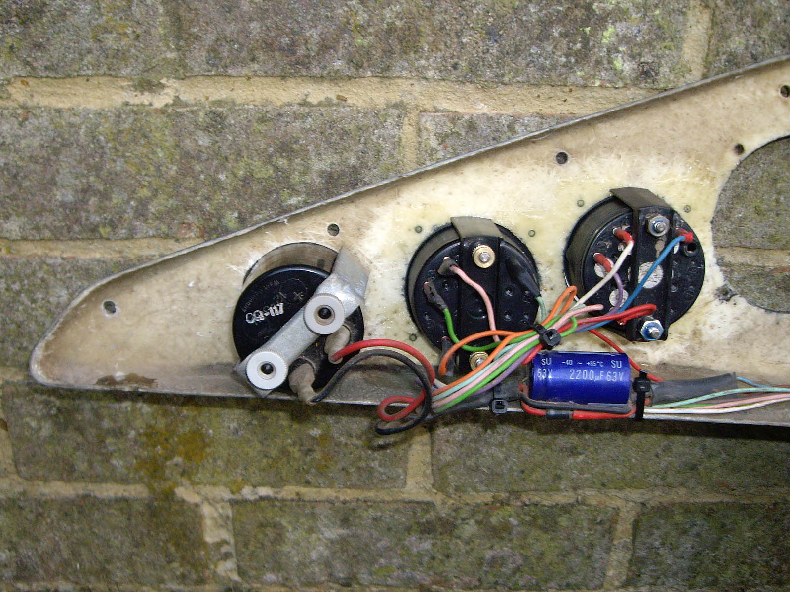
I’ve not finished the whole panel yet but at least I’ve done all the electrical work. Here are a few pics to finish off showing where I’ve got to. First, a general view of the back of the panel.

null

On the whole I’m very pleased with it so far because I’m a great believer in the old maxim ‘if it looks right, it is right’. Now the backs of the hour meter and temperature gauges.

null

The connections on the back of the new dual EGT gauge in the centre aren’t up to scratch, unlike those on the dual CHT gauge on the right, so I still have to redo those. The hour meter on the left has a reading of over 5000 hours on it, considerably more than MYRO’s 2000 or so. It doesn’t really matter because the gauge is only used to calculate the figures for the log books but I may replace it, I don’t know. I couldn’t use MYRO’s old hour meter because it was the wrong shape. Next, here’s the wiring for the master switch, main fuse and starter switch. I’m very pleased with it – I think it’s quite neat 😉

null

The same goes for the next shot which shows the backs of the RPM and fuel pressure gauge and the wiring for the fuel pump switch and fuse.

null

The original RPM gauge connections that I replaced were awful, to put it mildly 🙂

Finally, a shot from the front of the panel. You can see the repairs I mentioned earlier, four little blobs around the RPM gauge and each of the temperature gauges.

null

The fuel pump switch is over on the left with its fuse next to it. The master switch is to the left of the starter with a neon that I hope will illuminate as soon as the master is switched on above it. I haven’t been able to test that yet. The main fuse is to the right of the starter.

Rotax specify that a 16A fuse is inserted in the line between the voltage regulator and the battery. There is one in the wiring I’ve taken from MYME but if I’m not mistaken, it’s in the wrong place! That’s a job for next time I think.

Blossom Dearie

This has nothing to do with microlights or G-MYRO but everything to do with the passage of time and the passing of youth. I just heard today that Blossom Dearie, the American jazz singer, passed away in February.

Back in the late 60s when I was very young, footloose and fancy free a few of us used to go to Ronnie Scott’s Jazz Club in Soho, London and we heard Blossom Dearie sing live there many times. How sad to know that she’s gone. Every time someone who you knew and loved in your youth passes away they take a little bit of your life with them that can never be replaced.

Here’s a Youtube link to Blossom singing live at Ronnie Scott’s at about the same time as I used to go there. She sounds exactly as I remember her. What a lovely lady with a smile in her voice.

Oh for some Summer weather

This afternoon I thought I’d get out the two instrument panels and wiring looms (MYME’s and the part of MYRO’s that I have) and start to trace cable colours and connections. Almost as soon as I put MYRO’s panel and cabling onto my patio table the wind suddenly whipped up and it began drizzling.

This continuous appalling weather is so depressing and it’s really slowed things down. I’ve lost so much time in the past few weeks. If it had been more settled I’m sure I would have been pretty close to having MYRO nearly finished by now 😡

Painful day

I just wish now that I’d never bothered fitting the electric start to the engine on Friday. It’ll be some time yet before I fit the engine so it wasn’t a job I had to do, but it severely messed up this past weekend. Sure enough, I woke up on Sunday still with a lot of discomfort in my back and having had two consecutive nights of badly disrupted sleep, so there was little chance of me getting much done on MYRO. Naturally the weather was perfect – sunny, not too hot, not too cool and just a light breeze. Just my luck – but I couldn’t let the weekend pass by without doing something.

Obviously I couldn’t do anything too heavy, and even bending over to pick anything up was very painful. That meant, of course, that almost everything I handled I dropped and then had to pick up again 😕

Everything I did was slow but by the end of the day I had managed to get a fair bit done. The starboard undercarriage drag link had been replaced at some time in the past and was still black, so I took it off and painted it white. Then I removed the nose wheel assembly and as well as cleaning everything up, removing some light corrosion from and painting the two small dampers and painting the fork tubes, while I had the wheel out, I also removed the bearings and re-packed them with fresh grease. So that was good 🙂

Unfortunately, when I refitted the nose wheel assembly I found that because the pod is not fully supported with the screen not being in place, it had dropped a bit and the edge of my nicely repaired and resculpted pod nose wheel hole had beem nipped by the steering stop when the wheel had been turned. This had slightly damaged one edge. When I lifted the pod and supported it from the fuselage top tube with string, it was well clear of the steering stop but by then it was too late. So it could have been avoided – I’ll know next time I fit an AX3 pod! The damage is only slight and could be left but as it’s fairly accessible with MYRO tilted back I’ll probably see if I can repair it again.

So the day ended up being far from a total loss, which is more than could be said for my back. With all the bending I had to do, it ended up very painful indeed and I couldn’t wait to get into a long hot shower.

There’s more…

Late yesterday afternoon, before I tackled the undercarriage link refit that I wrote about below, I fitted the electric starter to the engine. Mark had removed it because originally he was looking to sell it separately, but I bought it as part of the total package because I need the whole engine with its ancillaries.

The engine has the carbs and exhaust manifold already fitted so it weighs a goodly amount but not too much to lift. So I moved it to where I could do the job and then carried it back into my garage afterwards.

I first noticed yesterday evening that I was feeling a bit stiff but this morning I could hardly move because obviously I’ve managed to pull a muscle in my back. Just my luck! The weather forecast for today (Saturday) and tomorrow is perfect for me to get lots done on MYRO and that’s what I’d hoped to do. But in fact, today I’ve been able to do almost nothing at all. OK, not quite nothing – because I couldn’t do any physical work I thought it would be a good idea to nip down and take a look at MZEL to check that I’ve refitted MYRO’s pod correctly. Let’s face it, if I installed MYRO’s instrument panel together with all the instruments and electrics and then had to take them all out again, that would give me a really bad day, so it was well worth doing 😕

null

All looks deceptively simple under there doesn’t it? I could hardly stand up again after taking the pic but in fact all was well and it also gave me a chance to talk microlights for an hour or so down at the strip, which was nice. I just hope that my back isn’t as painful tomorrow and that I can get a few things done. I have in mind a little bit of light painting to finish off the tubes 🙂

Feel like a complete pillock

I just put the following up as a post on the BMAA forum.

“On the AX3 there are links each side the tops of which are connected to the cockpit frame tubes and the bottoms to the main undercarriage wheel hubs. Because they pass through the pod, to remove the pod you have to disconnect the top of each one and let it drop it down.

After refitting the pod you have to reverse the procedure. The tube from which the links are fabricated is of course round and because the tops are enclosed in the brackets that secure them to the frame, which are an inverted simple U shape, there has to be a shaped plastic spacer on each side of the tube, within the brackets. So the bolt that holds them passes though the side of the bracket, through a spacer, through the tube, through the other spacer and out of the other side of the bracket. And access is through a restricted space at the side of the pod, from above and below.

Well, this evening I’ve spent about 2 hours just getting one of them reconnected. Getting all of the holes lined up was virtually impossible and I’ve been heaving, pushing, cursing, swearing, sweating – just about everything you can think of except get the job done. I got to the point where I was just about ready to set fire to MYRO and walk away but then I thought, what happens if I disconnect the bottom, undercarriage end.

So I did and it all lined up and went together in about 10 seconds.

I have never felt such a total pillock in all my life. I think it’s what’s called a learning curve” 😕

A podacious weekend

And one when for the first time for many weeks I managed to get everything done that I wanted to. Late on Friday afternoon I had been doing a bit more to the gel coat and had left the pod standing up on its end leaning against something. It was a bad mistake because the wind was gusting quite strongly and as soon as I turned my back, I heard a thump and it had been blown over onto its bottom. I thought that being fibreglass and it having fallen onto grass, no damage would have been done, but when I inspected it later I found that not only had one of the gel coat splits that I had repaired low down towards the nose cracked out again but now there was also another similar one on the other side. And to make things worse, the force involved had been sufficient for the underlying cracks to also penetrate the fibre mat beneath.

I was really mad but there was nothing I could do except repair the gel coat again and add strengthening inside. So that’s what I did on Saturday as well as get the whole pod ready for finishing and order a replacemant electric valve for our washing machine, but I won’t go into that 😀

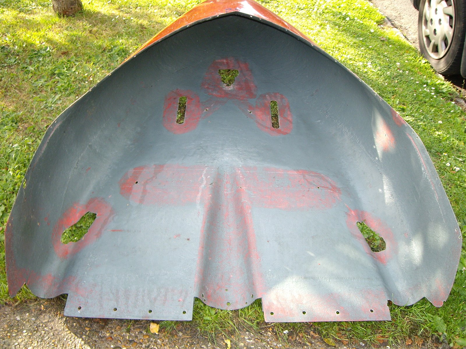
So by Sunday the pod was ready for final finishing. Here’s how it looked inside with all of the cloth patches that I’d added for strengthening and repairs.

null

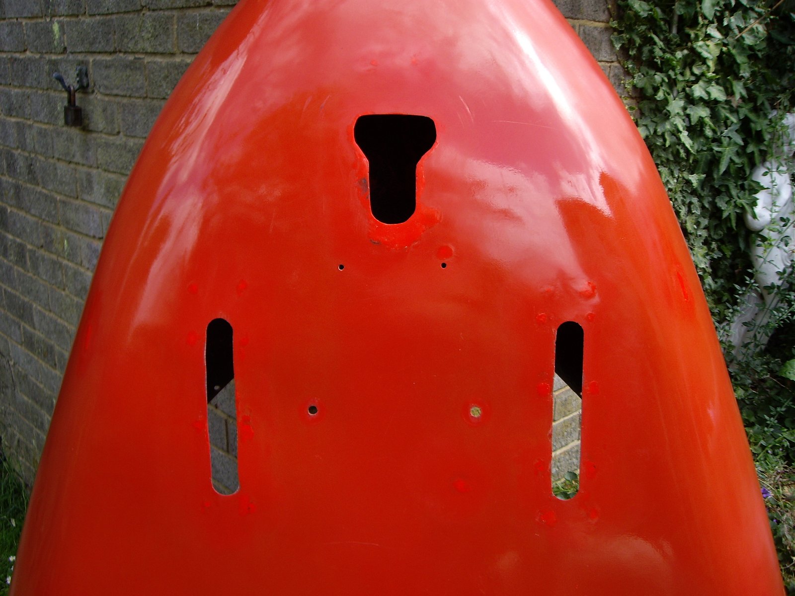
And here’s how it looked on the outside after I’d finished rubbing it down with very fine wet and dry to remove the old lettering.

null

The bottom still looked a bit of a mess though, as you can see from the next two pics.

null

null

In the above pic you can see how I’d repaired and re-shaped the hole for the front forks but what you can’t see is how I’d also added a lot of thickness and strengthening around it. Also visible are the repairs I did to the screw holes around the slots for the rudder pedal extensions. No matter how hard I tried, it was impossible to disguise these and I found in the end it was best to leave the gel coat filler a bit proud as every time I rubbed it right down flat the holes became visible again as black circles.

In fact the repairs to the pod bottom didn’t come out quite as badly as I’d first feared. The next pic shows the how the big split repairs came out.

null

And after a bit of buffing and polishing, even the nose section didn’t come out too badly either.

null

And it looks even better if you stand back a bit as shown in the next pic because, of course, nobody will ever see the bottom of the pod close up, unless I run over them that is 😕

null

Now one final shot of the pod taken from one side, after buffing and T-Cutting but before final finishing. As you can see, the old lettering came off pretty well really.

null

And now a shot from a similar angle after finishing. I went for a shade of grey for the inside that was lighter than the original as I think it will make the interior, which is a bit cramped at the best of times, a little bit more light and airy. I also cut the outside back again with the coloured T-Cut that you can get now – in this case dark red, of course. See what you think.

null

I’m quite pleased with the results, especially given the age and original condition of the pod and the fact that I’ve managed to avoid spraying it. The next pic shows the lighter shade of grey that I used for the interior.

null

And now to finish off, a shot of two of the smaller repairs that I showed right at the beginning, now completed. Although they are still a bit ‘bright’ at this stage, I’m confident that they will tone down and fade back to be closer to the colour of the surrounding old gel coat.

null

Now onto what for me was the best bit of the day. I dearly hoped that the weather would hold long enough into the evening for me to get the pod refitted to the fuselage frame and for once my wish was granted.

null

It was a bit tricky getting it on and with everything lined up so bolt holes matched bolt positions. Luckily just as I was lifting the pod up and wondering how I was going to support it while I tried to jiggle it into position, Steve, a neighbour, walked by and was quickly pressed into service. Things became slightly harder because by now I was beginning to tire at the end of a fairly long day but I’m glad to say that I got the pod refitted with minimal damage. I was also glad that the resculpturing work I’d done around the nose wheel hole and also the holes at the back (which I’d reduced in size and reshaped so they matched) went on perfectly without needing any adjustment of any kind.

Now one final shot showing the pod interior.

null

I’m very pleased with the new lighter interior colour and I also love the way the now shiny white pedals show up against it. But the very best thing of all is that this now means that I’m firmly into the rebuilding phase. I expect that it will not be without its problems but it’s great to know that from now on stuff is being stuck back on because everything that’s refitted means that I’m a little bit closer to the time when MYRO will be back flying again. And that just can’t come soon enough 😆

Dreadful July!

What appalling weather we’ve had here in South-East England this month. Cold, wet and windy – more like Autumn. I applied a little bit of gel coat filler to try to finish off late yesterday afternoon and just after I did it, it began to rain. So I moved the pod into my garage and when I got it out this morning it had been so cold that it still hadn’t cured.

And after predicting that we would have a ‘long, hot ‘barbecue’ summer’, the Weather Men now say that they got it wrong and that we’ll have more of the same of what we got in July, in August too.

Will we ever have a Summer? 😕

Tricky decision

But I think I’ve done the right thing and I’ll come back to that in a moment or two. I’m still working on the pod – I had hoped to be finished by yesterday but the weather was just not good enough. We had steady light rain almost all day which meant I couldn’t work outside and my space to work inside in my conservatory is rather restricted. I managed to get a bit done but not enough 😕

So I grabbed the opportunity to do a bit more from late this aftenoon through into the early evening. I won’t show any pics until I’m ready but work both inside and outside is now nearly complete. I have had to reluctantly come to the conclusion that I will be unable to achieve the level of perfection that I would have liked. It is, after all, an old pod that has been round the block a few times. It has got marks, areas of discolouration, scrapes, digs and imperfections almost all over and much as I would have liked to deal with them all and make them perfect again, this just will not be possible.

I originally intended to hack out and repair all of the gel coat cobweb crazing on the top of the pod but I now realise after doing the repairs to the bottom that this would be an impossible task. For a start, the gel coat filler I’ve got isn’t a sufficiently good match to the exisiting colour. It’s close, especially if you rub down to the original, unfaded gel but not quite close enough. It doesn’t matter on the bottom because nobody will ever see that close up, but it would be a terrible eyesore on the top. So I’ll just have to live with the crazing, which is not that bad and is a natural thing anyway. And I’ve seen much worse on some much newer microlight pods, I can tell you.

At least the pod is now good and solid with no cracks or splits. I found one last small one today just under ther lower mounting hole for the electric fuel pump where the nut when tightened pulls the curve of the pod side flat. I whacked a few layers of cloth on the inside which will sort that problem out and I’ll add a bit of gel coat filler on the outside tomorrow. And that’s when I had to make my tricky decision.

Ever since I’ve known MYRO, it has had the words ‘Cyclone AX3’ in non-standard vinyl lettering on either side of the pod nose as you can see in the header image. Now, unless your alternative is very good (and I don’t think this was) it’s never a good idea to use anything non-standard in a prominent place – like the nose of a microlight for instance 😀

I had started to remove the lettering a while back and I finished the job yesterday. Shock horror. Because the lettering had been on years and the gel coat underneath was still practically as good as new, it was as though the lettering was still there and had just changed colour 😯

My initial reaction was one of despair. I couldn’t see any way out other than having the outside of the pod sprayed which is precisely what I’ve been trying to avoid. Then I had a couple of thoughts. Where I’ve rubbed and buffed the gel coat on and around the repairs I’ve done, it’s come up much brighter. So I thought, to heck with it – if I have the pod sprayed I’ll have to rub it down all over, so why not rub it done anyway but with fine wet-and-dry, and try to remove the outline of the lettering while doing so. So that’s what I did this evening. I used 400 and (finer) 600 and carefully rubbed down the whole of the top of the pod. Why was it a tricky decision? Because if I’d got a bit over-enthusiastic at any point and rubbed through the gel coat, then it would have been ruined and would have had to be sprayed.

However, that didn’t happen and on initial appearances, the idea seems to have more or less worked. I’ll know for sure tomorrow when I’ve finished repairing that little split I’ve mentioned, finished the pod rubbing down with 600 and 800 grade wet-and-dry and buffed it up. So watch this space – and see if your face is reflected in the shine 😉

A step forward

We’ve had awful weather since I last did anything on MYRO and as I have to work outside I’ve been unable to make much progress at all. As it was quiet, I managed to make a start on sorting out the pod problems late yesterday afternoon and by the evening I was more happy. I managed to get rid of all of the excess gel coat filler and get another application done so I was in a much more positive frame of mind when I put the pod back in the garage for the night.

And today I got some more done. I’m finding that the gel coat filler is not sticking to the underlying fibreglass as well as I would like it to. I made and used two mixes today. I was just about to start applying the first one when it began raining out of a clear blue sky! Before I knew it the pod was covered in rain drops so I had to leave the mixed filler and get it under cover a bit smartish. By the time the rain had stopped and I’d managed to get going, the mixed filler had been standing for over 5 minutes, so I lost that amount of work time and the filler began to go hard in the pot before I’d finished. That was annoying enough but the second batch, as I was adding the catalyst, my hand was jogged and I put a bit too much in. So that went off too quickly too.

It also became very hard quite quickly and when I came to rub it down, I found it almost impossible to do so by hand. Fortunately I got hold of a little 180W electric detail sander. I was sceptical to start off with as I thought it would sand very quickly and be through the gel coat in no time. But no! It worked incredibly well and was an excellent way to get the excess filler down to the level of the main coat. Unfortunately, as tends to happen though, I got a bit too confident and while I was sanding the last tricky area (one of the two splits) I didn’t pay enough attention and managed to rub the gel coat next to my repair. I applied some more afterwards and if the weather’s fine I’ll have to see how it looks tomorrow when I get the sander going again.

I have to say that as a result of getting that little sander, I was much more pleased with the appearance of the results of my work than I had been up to then. So that’s good. I feel as though I’ve made another positive step forward 😀

Mixed day

Our Trike was collected and went off with its new owner today. He’s a very nice chap, Les from Shropshire, and I think he’ll finish what we started and get Our Trike in the air where it belongs. At least I hope so, very much. So that’s good. 🙂

First attempt at doing the work to the coloured gel coat on the bottom of MYRO’s pod was almost an unmitigated total disaster. Temperature was too low today and I should never have started it. Coloured filler on and all round the areas I want to fix and it wouldn’t go off properly. Then when I tried to remove the excess from the existing good surface, that was impossible to do completely and in the process much of the filler that I’d applied came out, especially from the two main cracks that I really wanted to fix. So that’s bad, very bad. 🙁

I’ve now made more work and I’m very annoyed with myself for pressing on when the conditions just weren’t good enough, and really I knew that 😡

Disorganised chaos

I kept toying with the idea of doing the fibreglassing inside the pod this evening but then deciding not to because of a dodgy weather forecast. But the weather kept staying warm and bright with not too much wind so I thought I’d make a start and see how much I could get done. I began by taking some coarse sandpaper and roughening up all the areas inside that pod that I’d removed the paint from to give the new resin a better key. Then it was time to prepare the fibreglass.

On the advice of Ted Snook and Laurie Hurman on the BMAA forums, I’d gone for fibreglass cloth rather than matting because it has a higher strength/weight factor. Rather than just blast ahead, cut the cloth and start sticking, I decided to take my time. First of all I put masking tape over the openings in all the areas where I was going to fibreglass so the resin couldn’t run through or round onto the outer gel coat. Then I made newspaper patterns for all the main sections of mat that I would be applying to the pod. There were 6 in all and something like 10 pieces in total including the little holes and other small areas that I will be repairing. Then I used the newspaper patterns to cut the pieces I needed out of the square metre of cloth that I had purchased. So far so good.

I looked up at the sky and it was a bit cloudy, but still sunny and bright, so I decided to go the whole hog and mix up some resin. From previous experience I estimated that I could get the whole job done in 45 minutes or less and it looked like the weather would be kind to me. As I mentioned in an earlier post, I decided to go for Epoxy resin for the internal pod work. It comes in 2 parts just like Polyester but doesn’t have anything like the smell. I took a paper cup and mixed up a reasonable measure. The ratio is a maximum of 5:1 (resin to hardener) and I would think my mix was a bit less than that.

The pod was on my back lawn and I started by laying in the mat around the nose wheel opening. Then, as if like magic, after about 30 seconds just as I’d got a nice old resin mess going with the cloth half in, it began to rain. Just what I needed. I grabbed the fibreglass cloth that was out on the patio table and sprinted with it into the conservatory. Then I grabbed the pod and did the same with that, the whole time with the dog closely on my heels, first into the conservatory, then out again, then back in. I placed the pod on the floor – not much room at all – and by now the rain was falling pretty hard and it had become quite dark. Far from ideal working conditions! Then the dog tried to push past me, the pod and the wet resin – he was very upset when he got a big flea in his ear and went off to lie down on his bed 🙁

To cut a long story short, somehow I managed to get the job finished and it didn’t end up looking too bad either. I didn’t like working with Epoxy initially but I warmed to it more as the job went on and I got more used to it. Certainly the relative lack of smell is a big bonus – especially as now because of lack of space, the pod is on the floor of my lounge while the resin hardens 😀

So having started off totally organised and with everything planned out nicely, because of the weather, the job and the evening descended into almost total chaos. But we got there in the end – leastways I think so. Haven’t checked whether the resin has gone off yet 😕

Get stripping..

I want to keep things moving along even if I can only do a little bit every day so today I wanted to make a start on stripping areas of paint off the inside of the pod where I want to do repairs and add a bit of strengthening. The eco-friendly paint stripper that I’m using turned out to be a a white gel that looks a lot like wallpaper paste. I put the pod on my lawn and set to brushing the stripper onto the areas I want to clear and after leaving it for half an hour or so – ie not that long – gave it a go with a paint scraper. I was actually quite surprised to find that a great deal of the paint had been attacked and was coming off so then I gave it a go with a piece of wire wool.

Then I moved the pod to where I could give it a wash off and hose down and was pleased to see that in the area of lawn where I’d done the job, a quick hosing removed all traces of the stripper and paint. The following pictures show how well the stripper worked.

null

null

null

null

They show that the method does work quite well. Obviously I’ll need to apply another application and although I have to be very careful about adding weight, I’ll probably expand and join up some of the areas. It’s not late as I type this so I’ll maybe have a quick bite and then give it another go.

It’s the pod, stupid…

The weather was hot and sunny late this afternoon so I decided I’d sneak off as it was quiet and start work on the pod. I really wanted to get some of the paint inside stripped off but almost as soon as I started, clouds began to brew and it began raining before I could get that far.

Even so, I managed to make some good progress. First job was to get the pod thoroughly clean and free of grease inside and out and get any bits and pieces of tape and stuff that had been stuck onto it over the years, off again. After the initial gunking, I took a few pics showing some of the fibreglass problems I’ve got to deal with.

This one shows some splits that have been caused by people climbing in and out and missing the cross-tube. The pic is taken from underneath and the rear of the pod is at the bottom.

null

The splits had just been gaffa taped over and the pic was taken just after the tape had been removed – with some difficulty I might add 😕

This next pic shows the same splits but from the inside.

null

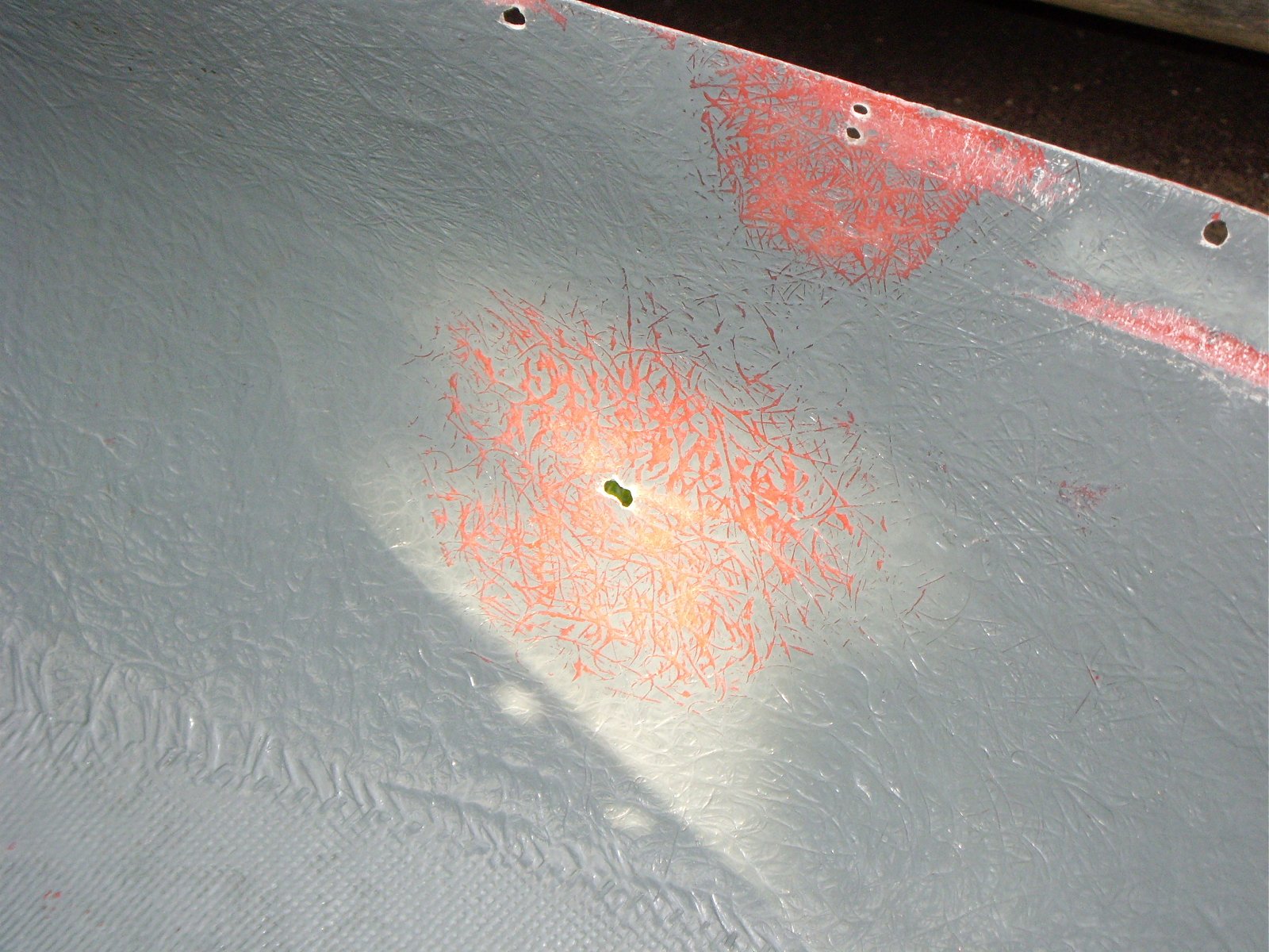
The next shot shows two problems – a small jagged hole that penetrates through to the inside and two smaller round holes one above the other at the top of the pic near to the pod edge that were possibly used at some time to take a small bracket.

null

And again, here’s a pic of the same small hole but taken from the inside this time.

null

This next shot shows a different kind of problem. Here the gel coat has been damaged, probably as the result of an impact, and over time it has begun to delaminate from the underlying fibre matting. This was taken from quite close up and the problem is by no means as big as it appears in the picture 🙂

null

To finish off, a couple of pics showing the front of the pod. In the next shot which is taken from underneath, the nose is towards the top and it shows the hole where the pivot tube for the front forks enters. There has at some time been some damage to the pivot tube hole which once again was gaffa taped over.

null

Here’s the same area of the pod, from the inside showing the pivot tube hole and also the slots where the extensions from the rudder pedals emerge to connect with the linkages that operate the front wheel steering. At some time something has been fixed to the steering slots, probably letter box draught excluders, to stop wind and muck entering the pod. Unnecessary you think? I have to say that when I was flying MYRO last year we landed on a strip where there were sheep and several lumps of sheep poo chose precisely that route to enter the pod and came straight at us at quite a few MPH, so I have to disagree 🙁

null

Although the above pics make the problems look pretty bad, in fact in fibreglass terms they are not too serious at all. After the shots had been taken I finished off washing the pod inside and out and its appearance immediately improved. Having now taken a close look though, I’m really glad I decided to completely remove the pod and do the work as it’s obvious that some of the things needing attention go back several years. Dealing with them can only make MYRO much, much better as a result 😀

Going going…

Our Trike sold on Ebay yesterday, for quite a bit less than it has cost us, but I feel as though I have ‘won’ with MYRO and you can’t have it all ways. The buyer was in touch earlier this evening and I’ll phone him tomorrow about arranging the pick up, so the deal will probably be done by the week-end as he lives in Shropshire.

Late this afternoon I nipped out to buy some large black and white cable ties as the ones I already have are a bit thin and short, and I also managed to find a tub of the special gel based paint stripper that you can use on fibreglass. So now I’m all set to make a start on the pod as soon as I get the chance. The feedback I’ve had on this paint stripper is a bit mixed to say the least. Some people have said it doesn’t work very well at all, but I have to give it a try as the normal solvent based stuff definitely cannot be used on fibreglass. I found another spray-on stripper that is fibreglass-safe on the Internet but that’s quite a bit more expensive, so I have to give this one a go first. Anyway, I’ll know in a day or so if it works or not and I’m looking forward now to getting cracking on the pod. If it comes up as well as I expect it will be a major leap forward 😉

Going back together

Slowly but surely 😉

The day started damp as expected but it brightened up and became warmer by mid-morning. There was still an annoying breeze which got quite strong on several occasions during the day but I just had to live with that. My target today was to get all of the white tubing in the fuselage area finished so I could make a start on refitting some of the items I had removed and I’m glad to say that I succeeded in doing that.

I lightly rubbed down the areas where I had applied primer with a very, very fine wet-and-dry paper and wiped them dry as I went. These included the small areas that had been deeply rubbed by the screen and pod and I wish that I’d thought to use white brushing primer rather than grey. Grey is difficult to cover with only a few light spray coats and as I’ve mentioned already, I want to keep the amount of paint I apply to the minimum for weight reasons. It wasn’t critical, though, because of course, the same areas will be covered again in due course by the screen and pod.

I masked the closely adjacent areas with masking tape and set to it. The paint I’m using is spray-on radiator white (yes, the stuff you get for household radiators) because I think that will hold its brightness well. It’s also a very close match to the existing tube colour and has pretty good covering power as it’s supposed to work without primer, although I never believe that 😕

Anyway, I was happy with the results that I achieved and after leaving the paint to harden off a bit in the hot sun, eventually I gave it a light T-Cutting. All a bit too soon, really, but it looked fine when I’d finished. Then I was able to start putting a few bits back on. I started with the seat bases, then the pedals and finally the throttle lever. I connected the brake and rudder cables to the pedals and I was glad that I’d thought to take pictures previously to remind myself how the cables were routed. I also had to decide which throttle lever to use, because I’ve got two. Rosie gave me the one from MZEL which is a standard lever but is a bit thin and flimsy to my mind. The BMAA must think so too because they recommend (insist on?) a modded version for aircraft used for training which is heavier and made from larger diameter tubing. MYRO had it when I last flew it but Rosie moved it into MZEL. Luckily, the one from MYME that I got off Mark at Galaxy was also a training version and that’s the one I decided to fit. It has an end plug missing from the passenger side but that should not be difficult to sort out.

So to finish off, here are a few pics taken at the end of my day’s work.

null

null

null

So things are now beginning to come back together and if the weather holds, it can only get quicker. The reason is that the next job is the pod and once that’s back on things will really start to get a shift on 😀

What a difference a week makes

Last Saturday was fine and hot and I made great progress on refurbishing MYRO’s front fuselage tubes. But as usual, things didn’t last. This year there was a glorious Wimbledon fortnight but immediately after on the Monday, the weather began to change and by Wednesday the weather turned really nasty. So we paid dearly for our few days of sunshine and since then the days have been cooler, cloudier and more blustery.

Today has continued in the same theme. After finishing off a couple of household jobs earlier in the day, I was looking forward to getting MYRO out and hopefully finishing off all the tube work. No chance. As I pulled MYRO out of my garage I could feel a light drizzle starting. So back in went MYRO and although I did manage to do a bit, it was in the confines of my garage. That meant I had very little room to work in, had to keep stepping over and around things all the time, kept banging my head on the pedals which I decided to give a hand-coat of white Hammerite and then hung from the roof while they dried and also had the wind blowing straight in through the front garage door while I was trying to spray-prime small sections of tube. I more or less managed but it wasn’t very satisfying and certainly wasn’t much fun.

It looks as though we could have a slightly damp start tomorrow but although the wind will still be with us, it should hopefully be dry during the daytime. I hope I’ll be able to finish off the tube work and be able to think about starting on the pod.

Incidentally, Our Trike is on Ebay and the auction ends tomorrow. It is £10 short of its reserve price and hasn’t budged for almost a day now. Usually with microlight auctions, nearly all the action comes on the last day and often in the last few minutes, so it looks as though Our Trike will be sold. Quite often, having been sold, microlights find their way back onto Ebay because of ‘time-wasters’ who bid but do not (or cannot) go through with the purchase. I hope that doesn’t happen with Our Trike, that it goes to a good new home and finds its way back into the air where it belongs.

After all this time

Although I’ve been saying I will do so for a long time, when I look back I haven’t posted a single picture of Our Trike almost since the very beginning. It’s rather ironic then that after all this time, this posting should contain the first and also what will probably be the last, as the ones I’ve included were taken to get a few to show in the Ebay listing that will hopefully allow us to find a new owner for Our Trike. But more of that in a moment.

As I expected, the fibreglassing items that I ordered at the end of last week to do the work on MYRO’s pod didn’t arrive in time for the weekend. That didn’t matter though as I still had plenty to do getting the paintwork on the fuselage tubes finished. So with the weather on Saturday still fine and hot, that’s what I got cracking on.

The main undercarriage beams on which the main wheels are mounted were in a rather scrappy state and after my previous de-greasing work I’d already rubbed them down and given them a light coat of primer. I have to remember at all times to be careful about adding excessive weight and painting is an easy source of that. I was going to finish them with an aerosol spray but access is a bit tricky, even with MYRO raised up on car ramps. The wind was making things even more difficult, so I decided to paint them by hand with White Hammerite. I was very happy with the result when I’d finished so I think I made the right choice. For once 🙂

I made good progress elsewhere too. I completely finished repainting the pedal assembly which ended up looking very good, and prepared all the sections of tube which had had their paint badly scratched or rubbed. And that was it for Saturday – another very satisfactory day’s work.

My plan for Sunday was to go out to Ken’s, re-fit Our Trike’s pod skirts, take it outside to take some pics and finally get an Ebay listing done. In the event I managed to do all that but with a bit of a break to watch some of the Wimbledon Men’s Singles Tennis Final, it was 1.30am before I eventually got to bed. A rather long day 😕

The first couple of pics show the workshop where Our Trike has resided for the last couple of years and the last ones were taken on Ken’s back lawn.

null

null

null

null

null

null

null

If you CLICK HERE you can see the page I created for Our Trike’s Ebay listing. And as I type this, it seems to be working pretty well. The listing went up just after midnight last night so hardly anyone would have seen it for several hours as they would have been in bed! I’ve just checked and after only 22 hours, there have been 4 bids (but all still under the reserve price), 323 visits and there are 43 watchers!

It’s encouraging and I hope that at the end of it Our Trike will go off to a good new home. Even so, after all this time I will miss her…

Gunk ain’t what it used to be…

Unless I’m mistaken that is. While the evenings are long and the weather so good, I’m trying to do a bit whenever I can. I picked up some very good advice from Ted Snook in a thread I started on the BMAA forum about renovating MYRO’s pod so I’ll be getting together the stuff I need for that over the coming few days. But this evening I’d decided that with the pod and much of the front end removed, I’d see about shifting some of the grease and muck that’s accumulated in and underneath MYRO over the years. I’d got hold of some Gunk engine degreaser earlier in the day to help do the job. I started off by doing the pedal assembly, then the front forks and then worked my way back to the undercarriage which was in a right old state. I even included the inner section of the rear fuselage cover that’s just behind the seats as that also had a distinctly greasy look, feel and smell about it.

Well it’s some time since I bought and used Gunk but I reckon it’s changed. It used to shift grease like magic and turned white when you washed it off with water. Now it doesn’t do either it appears. Presumably the product has been made more ‘environmentally friendly’ with the result that it now doesn’t do the job it’s supposed to half as well as before 😕

Anyway, I did the best I could and after washing all of the treated areas with warm water containing detergent, I finished off by carefully hosing it all with cold tap water. A quick dry off and although there were still a few greasy patches on some of the more inaccessible parts of the undercarriage, the results made it well worth the effort.

So progress is still quite brisk. I have to get all the parts I treated this evening really clean and grease-free so I can spray a bit of paint on the bits that need it. Then when I’ve done the pod – next week-end maybe – I’ll actually be at the stage where I’m rebuilding. That’s an exciting prospect 😀

Excellent day!

In more ways than one. It’s been a bit of a scorcher and as I type this we’re paying for that. It started with a few rolls of thunder then it went from rain to hail and it’s now back to a steady downpour. But I also had an excellent day as far as MYRO is concerned.

I wanted to feel that I was moving forward constructively so I thought I’d make a start by fitting the new engine mountings, the voltage rectifier and the starter solenoid. The latter two items I got from Mark at Galaxy and when I had a look at them a few days ago, I found that both had slightly rusty screws fixing them to the bracket on which they are mounted. I had given them a couple of blasts of WD-40 in the hope that this would ease them as both had to be removed to get access to the bolts holding the bracket to the main tube and it had worked a treat.

I was slightly concerned about the new engine mountings though. Because the engine tries to rotate in the opposite direction to the propeller, one set of mountings has to go on top of the engine brackets and the other set underneath. The engine brackets are made from a 90 deg section alloy extrusion and because the dimensions are limited, the mountings that go underneath must have the edge that goes against the upright of the bracket trimmed off. When I fitted them, however, I found that even with the edges trimmed, both mountings sat slightly proud of the surface on that side because they still slightly fouled the inner curve of the extrusion. I found that the scope for further trimming was rather limited so I gave one a bit of a file to get it to sit down as far as I could, which was about the same as the other did anyway, and fitted them both. Most likely nobody else would have worried about it! Here are a couple of pics showing this part of the day’s work.

null

null

By the way, the other unit that’s mounted on two brackets behind the engine is the fuel pump.

Now, I haven’t yet got the official go-ahead to replace the screen and door plastics but the job will have to be done anyway, so I thought I’d make a start. Step one was to take the doors off which was easy enough as they are mounted on piano-type hinges with a long pin that’s inserted from the top and goes through the length of the hinge. By removing the pins, the doors come straight off.

Step two was removing the screen. The screen is attached to the fuselage upright tubes with cable ties so those only needed cutting with a Stanley knife. It’s also attached to the pod with a combination of plastic bolts and cable ties and I was pleasantly surprised to find that because a flat of each inner nut was against the inner upper surface of the instrument panel, all of the plastic bolts could be removed single-handedly from the outside. Snipping the cable ties then freed-up the complete instrument panel which could then be carefully removed. Once again, here are a few pics of this stage of the work.

null

null

null

I’d originally thought about removing the pod completely to do any renovations and renewals to it conveniently off the airframe. However, I thought that if I just removed the pedal assembly, which needs a bit of de-rusting and repainting, this would give me enough access to the interior of the pod to do all of the work I needed to do. So out came the pedals.

But then I got to thinking again. I doubt anyone will have this much of a chance ever again to do the thorough job on MYRO that it needs. So should I remove the pod after all? I agonised for some time, as it meant removing the front forks and wheel as well as four pod mounts, two undercarriage trailing links and the ties between the rear of the pod and the bottom of the fuselage covers. Then I recalled the advice I gave to someone a few days ago about something they were worried about doing, which was, ‘Just Go For It!’ So that’s what I did and here are the resulting pics.

null

null

Once I’d got it off I knew that I’d done the right thing. It’ll be easy now to clean and renovate the pod itself, and I might even go through with my original idea of having it re-sprayed. Have to be careful about the weight though. And now cleaning and repainting the pod floor tubes will be a doddle as well.

So that was the end of day one and I was really pleased with the progress I’d made, despite the large numbers of small boys who all wanted to know what I was working on and what I was doing. Taken all round, an excellent day 😀

Yipee!

I know it doesn’t look like much, but just take a look at this pic.

null

Yesterday I received the air filters I need plus the throttle and choke cables that were originally connected to my engine, from Mark at Galaxy. So now, when the bits shown in this pic, which arrived today, are added to all the other stuff I have in my garage, I’ve finally got everything I need (ahem…. except for a prop 😕 ) to get MYRO back in the air! To say I’m thrilled would be an understatement – I’m absolutely over the moon 🙂

I was thinking about actually fitting the engine mounts this evening but I decided not to. Best to do things properly a step at a time starting this week-end. Doing things half-baked is when you make mistakes and I don’t want to do that.

The W002 Repair Form that I sent off to the BMAA about fitting new screen and door plastics plopped back on my doormat a day or so ago. Seems I stupidly failed to notice that I have to get the form signed by the Inspector who will check MYRO out in due course, so as we’ve already spoken a few times in the past (about Our Trike), I gave him a call and popped the form in the post to him. That will be the last ‘major’ airframe purchase I have to make, I think, and I’ve already been told by someone who recently did the job that it comes in at only £70-80. Well worth it I think in terms of achieving a considerable appearance upgrade.

So that’s it! Yipee – I’ve got more or less the whole of this week-end to myself and I can’t wait to get going 😀

Getting the show on the road ….. at last

Several days ago I phoned Bill Sherlock to ask about replacing the clear polycarbonate in MYRO’s screen and door panels and he kindly advised me of the required thicknesses – 1.5mm for the screen and 1.0mm for the door panels. I had got hold of that information from elsewhere and really just wanted authoritative confirmation that it was correct. However, I was very glad that I’d phoned him for another reason. Ordinarily I would then have blasted merrily away, got hold of the plastic and done the job. He wisely cautioned against doing that in view of a recent incident when a door that had been recently repaired in such a way fell off an AX3 while in flight, narrowly missing a person on the ground.

He suggested that I downloaded and submitted a BMAA W002 repair form to the BMAA Technical Office covering the work to be done. So that’s what I did a few days ago, and now I’m waiting for a response. I don’t see how the repair can be prevented or whatever, but it does officially flag it up to the BMAA Inspector who will eventually inspect MYRO for its PTF (Permit to Fly) and will then be able to pay special attention to the completed work to ensure that it fully meets all the requirements for safe flight. I would be happy with that 😉

And I’ve also made some more progress today. Yesterday, as the weather was so good, I decided to pop down to the strip, not to fly but to take the reference pics of MZEL that I will need to help me put MYRO back together. I was surprised when I arrived at the strip in the mid-afternoon to find that it was almost deserted. There was just one owner who had not long returned from a flight and was cleaning the front of his aircraft, and that’s all! What a shame as at the time, it was glorious for flying. Trouble was, the weather forecast had said that it would be dull, clouding over and with a chance of occasional light showers 🙁

Frankly, it could not have been more wrong. Isn’t it incredible that even with all of the technolgy that’s available, apparently it’s still impossible to make a reliable area forecast for just a mere few hours ahead. The mind boggles 😕

Anyway, I got the pics I needed using flash in the hangar without having to pull MZEL out into the open. Then today, armed with them and the AX3 Parts Manual, I was able to make an initial list of the components I need to make a start on getting MYRO back together, in particular getting the engine mounted on the fuselage. Then I phoned P & M Aviation and emailed it over. Hopefully they’ll have everything I need in stock and with a bit of luck I’ll hear from them tomorrow to give them my card number so the items can be despatched. After that I got onto the ConAir web site and ordered the twin EGT gauge that I need. Rosie said that the twin CHT gauge that’s still in MYRO should work OK as she thinks that previous problems were down to the sensors that I have replaced, of course, with the ones on the wiring loom I got from Mark at Galaxy. I also ordered some high temperature red silicone for the exhaust manifold joint, so pretty soon I should have everything to hand to make a proper start on the work.

The first steps in most projects are small ones as in this case, but hopefully pretty soon I’ll have things moving along a bit more briskly. The show is at last getting on the road 🙂