
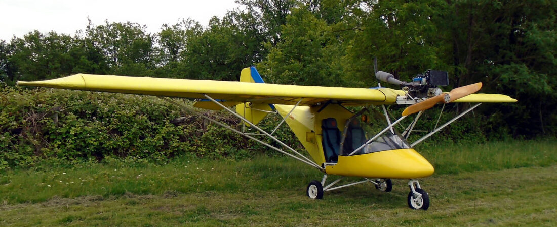


Quite a few things have come together over the past three or four days which means that MYRO has really moved along. And one of the good things as far as I’m concerned is that it’s been too windy to fly anyway so I don’t feel as though I’ve missed anything. While I was working outside today a flexwing flew over looking decidedly side-ways in the wind! Hopefully he found somewhere to land that’s a bit more sheltered than where we live.
A week or so ago I started a thread on the BMAA forum asking how I should wire up MYRO’s engine hour meter. It expanded into talking about the wiring in general, which is why I posted my wiring diagrams, and I got some very good advice. Amongst other things, whereas I wasn’t going to add any electrical sockets to the panel because I don’t know what I’ll be needing in the future, the consensus was that I should add some now. The one I especially didn’t want to add is a car cigarette lighter socket but it turns out that that’s actually the one you should have because so many accessories (eg GPS’s) come with a car cigarette lighter plug. So I decided to go for two DIN sockets and a car cigarette lighter socket and the bits arrived on Friday.
I did an extension to the wiring diagram that had them all fused and connected on the switched side of the master switch so in MYRO the master switch really is just that. Nothing will become live unless that switch is turned on. I also placed them in a stack on the right hand lower part of the panel so there’s a nice space to the left where I can position my radio. Originally in MYRO the radio was mounted far too low down for my taste and the old Icom that I was using was far from being the easiest model to use anyway because of its small, hard to read screen and horrible tiny little buttons. Don’t tell Rosie I said so, though 😉
Following a very informative thread on the BMAA forum by Rick Moss about installing the CAA charts in a cheap car satnav I’ve also bought and converted one myself. I’ll talk about it in more detail in another posting but it works brilliantly and my initial experiments indicate that it will mount extremely well right in front of you where you want it using its suction mount on the top of the panel. Another small step forward 🙂
I was a bit disappointed actually with the new panel sockets and fuse holders. The fuse holders were bigger than I expected them to be and not of very high quality. The plastic thread of the first one I fitted almost stripped when I tightened down its metal nut so I was very careful with the other two. When I’d finished, I also ‘locked’ them by adding a few drops of epoxy resin to the threads and to the nuts where they were in contact with the back of the panel. and I did the same to be sure with the other sockets too.
I was also disappointed to find that although the DIN sockets looked very nice with little flip up covers, because theye are designed to mount in a metal fascia, they have no earth tags. This meant that I had to solder my earth connections directly to the bodies of the two sockets which was time consuming and also involved their getting very hot. However, it worked and no harm appears to have been done. If I’d thought maybe I should have soldered the connections to the nuts instead while they were removed, but I didn’t 😕
Here are a couple of pics showing the absolute final, finished panel. The first is a composite showing close-ups of the panel back and front and the second is a general shot of the whole panel.


The only small point of concern is that since I finished the panel wiring, Andy Buchan with his Inspector’s hat on, said that he thinks the relevant BMAA TIL only allows 2 x power sockets, with fairly low total currents drawn from them. He suggests that I put 3 on the form and see what happens – there is a degree of give and take – but check what current I want each power socket to be able to draw and placard and fuse accordingly. So I’m hoping that the worst I’ll need is a placard saying that only two should be used at any time and the maximum load must not exceed 12 amps (say).
Now what else? Today I removed the starboard main undercarriage hub, repacked the bearings with grease and lubricated the brake mechanism, which was luckily in good working order. I also adjusted both brake cables up. Then I got under MYRO and gave the undercarriage cables, which were very dry, a light coating of grease.
Earlier on before I got ‘dirty’, I finished off the last little bit of painting at the front of the fuselage main tube and the tops of the two tubes that support the engine mounts. This is all extremely good news because it now means that MYRO is ready to have its panel and wiring loom installed.
Like I said, things really are now moving on apace 😀
 English
 Nederlands
 Français
 Deutsch
 Italiano
 Latviešu valoda
 Português
 Español