Raring to go

Nipped down to the field today to pick up MYRO’s logs and other papers that Rosie still had. The temperature was below freezing and I was surprised to see just how much snow there still was on the open area in front of the hangars and on the runway itself. The field is at the roughly the same altitude as our house but whereas we now have just the remains of the light dusting from New Years Eve, the field still has a couple of inches of cover at least. I guess it’s because it’s closer to the coast and is the first area to be hit when the winds bring in wintery weather from the east.

It was good to be back there though as I haven’t flown for several months because of the time spent working on MYRO right through the summer whenever the weather was good enough. I just couldn’t afford to miss any opportunity and I know that it will be worth it in the long run. As always, although there was no flying going on, there was someone there to chat with and that’s all part of the fun. The dog became very impatient because all he wanted to do was go off to investigate all the interesting scents around the place, so eventually we did. Rosie’s trailer was more or less where I left it when I returned it after picking up MYRO but she had made little progress on re-erecting her polytunnel hangar and part of what had gone up looked to have been blown down again with some tubes looking a bit bent and slightly the worse for wear.

But there’s just something about being back on the airfield among aircraft. Time flies and pretty soon we’ll be taken by surprise as always when the green shoots of spring start to emerge. I can hardly wait this year and I’ll be raring to go to get back up there along with MYRO 🙂

Here’s to a happy 2010

We’ve had some awful cold, wet, windy weather since my last posting which is no fun believe me when you have to walk a very active dog three or four times a day and every time he comes back soaking wet and plastered with mud and muck. But we’ve managed to get through it while still retaining (most) of our sense of humour and last night I enjoyed the pleasure of seeing in the New Year with a few friends over a nice meal, a few glasses of wine and some lively conversation.

2009 was not without its sadnesses. A very old friend went on holiday to Spain almost exactly a year ago with his wife and a couple of friends and unfortunately never returned. He’s greatly missed by all of us and will always be so. And in November I attended the funeral of my father-in-law. In some respects I was lucky that I was only touched twice by such events in 2009 because several of my friends have told me that they lost a number of people who they were close to during the year.

But on the brighter side, my mother who was 90 this year moved down to live with my sister and her husband and when I visited her on Monday last for the first time since her move she was looking really bright and well, so that’s a blessing. Also, although none of us knows for sure how much longer the effects of the credit crunch and the recession will last, I’m fortunate in that my own business seems to have weathered the worst of the storm fairly well and I have some interesting new developments coming along in the pipeline which I hope will make additional new contributions in 2010, one of which I’ll be sharing here in due course as it’s microlight related.

But the main issue for 2010 will, of course, be MYRO. I still need to find somewhere to keep and fly MYRO from and this will become more pressing once the weather begins to improve. I’ll shortly be tackling my friend again about whether I’ll be able to put MYRO onto his property in Kent and that would be my preferred choice even though the landing and take off distances are all a bit short. But even if I couldn’t keep MYRO there for the long term, it would be a good place to finish the final assembly and get the wings back on so it’s ready for Permitting. Someone mentioned a couple of possible locations in Essex a few weeks ago and I think I’ll follow those up too. The only thing is that if I had to go that route, the expense involved could mean I’d have to sell one or more shares in MYRO off which I’d prefer not to do if I could avoid it. But we’ll have to see.

I’m typing this looking out at a day that’s cold with a clear blue sky and with a light sprinkling of powdery snow on the ground from last night. So as usual we come back to the weather. 2009 was another generally poor year for microlight flying although from the comments made by a few on the BMAA forums, some pilots still managed to get quite a few hours in. I hope that today is a harbinger of things to come weather-wise in 2010 and that we can look forward to many more days without rain, low cloud and high winds than we enjoyed in 2009.

So on that note here’s wishing everyone a happy, safe and peaceful 2010.

Ahhh Winter…

Our house is at what I think is the highest point in Kent and yesterday there was a snow warning for our region. Unusual really, because usually the South East doesn’t get much extreme weather but this time the wind is from the east and is bringing with it very cold air from the Continent.

Anyway, it happened and this morning we’ve got about 8 inches (18-20cms) of snow. Toddie, my dog is delighted – we’ve been out in it and he was leaping about like a puppy and he’s 11 next birthday.

The local kids have all got a day off school and they’re out with sledges and snowballs and a neighbour’s nippers who are the loveliest pair of kids you could ever wish to know, came rushing over to play with the dog and threaten me with huge handfuls of the white stuff.

The roads are passable but there’s very little traffic and it’s beautifully quiet – really marvellous with these conditions as although it’s clouding up again now, when we were out earlier there was a break and the sky was blue with bright sunshine.

Later on I expect there will be snowmen all around as the kids were already busy with their constructions and a few giant snowballs that will stay there for days after the main snow has melted.

Marvellous – just the way winter was when we were kids and hopefully always will be. What a joy.

But am I glad that I wasn’t able to get MYRO out of my garage and into all this stuff. Far better for it and its wings to be where they are until the first shoots of Spring and more ‘sympathetic’ weather come along 😉

Marking time with crossed fingers

So here we are just coming up to the end of November and, of course, with Christmas just around the corner too. Work on MYRO came to a complete halt at the end of October really and I’ve hardly even opened the garage door this month, let alone done any more work on it. And it’s just as well really. Weather-wise November has been an appalling month. We’ve had an amazing amount of high winds and much of the time these have also been accompanied by continuous intense downpours of rain. This was felt most painfully in the Borders area in the North of England where Cockermouth and Workington suffered heavy flooding, homes, businesses and, sadly, lives were lost and even heavy stone bridges were washed away by the overflowing rivers. My own experiences with my MYRO project effectively shelved now until the Spring pale into insignificance in comparison.

Without having somewhere to keep MYRO where I could fit its wings, it was impossible for me to go ahead and do so anyway, but in a way, it was fortunate that I could not under the circumstances. If I had done, MYRO would have been standing out in all this weather which would have made me very sad and annoyed after all the work I’ve done. As it is, the wings in the hangar in Canterbury and MYRO in my garage, can stay where they are now until the weather improves.

At the time of writing, I haven’t taken any further steps to inhibit MYRO’s engine. However, I don’t think the danger of internal corrosion is very great. The metal tools hanging on my garage wall, which have no corrosion protection at all, are not going rusty so I can’t see why it should be any different for MYRO’s engine. I’m not so sure that that’s true, though, for the X-Air (see the Galleries page) that I bought well over a year ago that Ken still has. It hasn’t flown now for over a year and I’m not sure that it has even been turned over or started regularly. For most of the time since it’s been down South it has lived in the open although I think it recently went into a hangar. When its Permit came up a few months ago there was a problem with corroded nuts and bolts which in many cases were worse than the ones I replaced on MYRO. These have been replaced on the X-Air but after that, I’d be rather concerned about the internal condition of the engine. But there you go, it’s not my worry I’m glad to say 😉

I haven’t heard anything from my friend about my keeping MYRO on his land in Kent and I’ll leave off phoning him for the time being. I recently asked another friend if he knows anyone with some suitable land where I could keep and fly MYRO from and he said he knows someone with a goodly size farm that would be suitable. He said he would find out whether he’d be agreeable and if so, that would be marvellous. The location is not too far from my home and it would be a much better one for taking off and landing as far as I can tell, as it doesn’t have any neighbours close by who might be overflown. I’m really keeping my fingers crossed on this one I can tell you 🙂

Good news, bad news

The good news is that with Winter approaching, MYRO’s fuselage is under cover in my nice dry garage and I’ve been given permission to leave the wings where they still are, hanging safely on a wall out of the weather inside a dry hangar. The bad news is that as I still haven’t managed to sort out a place where I can keep and fly MYRO from, that’s where they’re now likely to stay until the Spring. But that’s better than last Winter when MYRO’s fuselage was outside partially covered by a tarpaulin in what seemed like never-ending rain.

The Credit Crunch which I had hoped would be beginning to recede by now is also actually getting worse, and not just for me I suspect. So budget is coming under quite a bit of pressure too and with Christmas only a few weeks away and taking everything into account, I think that MYRO and microlighting will have to go onto the back burner until the New Year. I’m very sad about that but I have to face facts and there’s not a great deal I can do about it.

I asked a few questions about inhibiting MYRO’s engine against internal corrosion as it has now been standing without being run for about a year. Although my garage is dry, there’s still an outside chance that crankcase condensation could cause corrosion to start on any internal bearing surfaces that have lost their oil protection. A can of special oil that you spray through the inlet and exhaust ports only costs a fiver but it means taking the exhaust and inlet manifolds that I’ve only just fitted, off again. I’ve been advised on the BMAA forum that just squirting 2-stroke oil in through the spark plug holes and turning the engine over a few times will probably be sufficient under the circumstances because the guys who know about these things say that it still manages to get where it’s needed. So I think that’s what I’ll do – I’ll leave the inlets and exhaust on and see if I can spin the engine on the starter. As the prop hasn’t been fitted I’ll have to be careful though.

Damn the Banks that caused all this grief and suffering for us all. Thanks to the dollops of taxpayers’ money that have been doled out to them, they aren’t feeling the pain. It’s just the rest of us who are the victims of their scheming and greed 🙁

Right prop-er

Here’s a picture of my prop

null

I love this prop. When I last flew MYRO it had the standard wooden 2-blader and I’ve been told that this one will give it a distinct edge in performance and/or fuel consumption. I got it off Ian MacAdam, a microlight instructor at Damyns Hall in Essex, who got it off a Rotax 503 like mine that was on a Spectrum which was blown over in a storm (sounds a bit like MYME, doesn’t it). So I more or less knew that it was going to be OK but had to make a quick decision to buy it because it was on offer at a very attractive price and would soon have been snapped up by someone else. Then the fun began.

I contacted LTS Ltd in Hampshire, the UK agents for Arplast. After some faffing around at my end I followed the instructions I was given and found the prop serial number which confirmed that the prop was indeed the correct one for my engine/gearbox/airframe combination. Then I looked on the BMAA web site and located the relevant MAAN for the approval only to find that the prop it specified was different. Back to LTS who confirmed that my prop is indeed the correct one and that there is therefore an error in the BMAA documentation! So onto the BMAA Tech Office who were initially sceptical and asked for a certificate of conformance. Back to LTS again who said that they were unwilling to issue such a certificate as although they do so now, they didn’t when my prop was sold (9 years ago).

Hmmm… decided I needed to be a bit more assertive as otherwise it looked as though too many petty barriers were being erected that could well have prevented me using this prop – and I was also by now getting a bit annoyed. Ian came back to me and confirmed the registration of the Spectrum that the prop had come off. I had already established that there was only one such aircraft on the G-INFO database but it was good to have the confirmation. I then found who the owner was when the prop was sold and – voila! – LTS managed to locate a copy of the actual sales invoice proving its bona-fides. I then suggested that Tech Office talk direct to LTS to confirm all this and back came an email in a day or so confirming that the prop had now been approved. Oh, and could I add an aircraft registration to the paperwork in due course as a precedent – that aircraft, G-MYME 😕

I was not amused by this. I knew that Mark had the prop hub and a single blade off MYME but it had proven too expensive to buy two more new blades to make a complete unit. It turns out that they are for exactly the same model prop as the one I have. My question is, if BMAA Tech Office knew that, why did I have to go through all that rigmarole to get THE SAME PROP accepted for MYRO? Just not an acceptable way to go about things in my book 🙁

Anyway, it’s done bar sending in the paperwork – oh, and a fee for £40 for the privelege!

PS… Want to hear a weird story? The person in whose name MYME (storm damaged, written off) was registered was also once the owner of the Spectrum (storm damaged, written off) that the prop came off. Strange but true 😯

So far, so good

I’m sitting in my (home) office and looking outside at the gorgeous still, sunny Autumn weather we are having that apparently will be with us for the next few days. Then I have this idea.

So I move the car and pull MYRO out. I can’t resist taking a couple more pics in the sunshine.

null

null

Then I get a 12V car battery that I have in the garage and connect it across MYRO’s battery terminals using jump leads. I flick the Master Switch and the neon glows. I try the fuel pump – yup, it starts so I switch it off immediately as it’s running dry, of course.

Then the big one. I turn the key to Mags Both and then turn it once more. The starter kicks and briefly turns the engine. OK, it’s what you would expect, but that’s the point.

My wiring, which was all done from scratch don’t forget, has passed its first big test. I won’t know for sure until there’s a proper battery fitted, the engine starts and runs and the electrical system charges. But so far, so good. That’ll do me for now 😉

Rain stopped play

Not quite, but almost.

By the time I’d done all the other little things I needed to for a Sunday it was 2.30-ish by the time I got out to the garage with a dull and threatening sky overhead. I pulled MYRO out, not too far luckily, and quickly whipped the exhaust silencer off to reposition the engine safety cable. After I’d done that I wanted to put the cylinder head air scoop on, so I grabbed it and gave it a good clean up. I couldn’t get the original colour back because, let’s face it, it’s been stuck up there in a pretty inhospitable environment exposed over the years to full sunlight (sunlight?) and a hot cylinder head. Even so, with a good rub over with turps followed by a polish with T-Cut I was amazed how bright and shiny it came up!

So I then clambered up on my small stepladders to begin fitting it and … you’ve guessed it … down came the rain. Only drizzle mind, but really heavy. I pushed MYRO back into the garage and tried to work inside but I couldn’t find my lead light and my large torch wasn’t bright enough. So after jumping around and cursing for a bit, I noticed the rain had stopped momentarily. Good game this – so out went MYRO again and on went the air scoop. Then I began to finish off all the cable-tying but before I could complete the job, down came the rain again. Really good game … back went MYRO but only under the opened garage door this time because now I could do the work under the shelter of the door. Hah!

So that was it – game over. I was very pleased with the way it turned out – by carefully cable-tying electrical wiring, fuel tubes and throttle and choke cables together I finished up with a neat arrangement that was also nice and firm so nothing could be chafed by vibration. You can see the finished article below.

null

null

null

null

null

The final job is securing the throttle cable to the cabin fuselage side tube so the throttle lever works but I had to leave that as I couldn’t open the door wide enough inside the garage to do the job. So next time I’ll have to do that and I’ll also have to sort through all the brackets etc for the tail assembly that I placed in order on the garage floor, where they have stayed since I removed them back in June. There are a few leaves and things on them now but they are all still there, laid out in order.

Amazing – only four months ago but it seems much longer. Not a bad Summer’s work I suppose, really 🙂

Carbs on

Just a quick post to mention that I stripped, cleaned and fitted the carburettors today. One had a little bit of a chalky deposit inside that was similar to what I found when I cleaned Our Trike’s carbs all those weeks ago, but nowhere near as bad. I got all the fuel hose connected, including the section that goes off to the fuel pressure gauge, so bar tidying everything up, the engine is more or less ready to go.

It didn’t take long to fit the choke cables but it was a devil of a job connecting the throttle cables. The reason was that the throttle slide is held down by a very long spring that has to be held fully compressed while the cable is passed through the carburettor top, the spring, a plastic sleeve that keeps the needle located, the needle clip itself and a small hole in the slide and then pulled over to one side to lock in place. There must be a trick to it that I don’t know about 😕

I cable-tied quite a few tubes and cables before it got dark this evening and I’ll finish the job off tomorrow. I also need to remove the exhaust silencer and re-fit the engine safety cable which I fitted the wrong side of the rubber exhaust mount. Then all I need do is clean up and fit the engine air scoop and MYRO is more or less done as far as the work I can do at home in my garage is concerned.

I’ll take pics tomorrow when I’ve done all that and you can bet I’ll find something else that will need doing. But I can begin to glimpse the end of the road in the distance …. 😉

New page added

I few months ago I commented in one of my posts about WordPress plugins. They’re the little extra pieces of software that are written by individuals and usually released for free that you add onto your main WordPress software to make it do clever things that weren’t originally built into the program. There are some cracking good ones out there (and some not so good ones too, but the least said about those the better) and I’ve been fortunate in finding several that I’ve used in My Trike. For example, the neat way that images open in a blacked-out screen in a choice of resolutions is done by a plugin called Shutter Reloaded.

Since I first got MYRO I’ve been keeping a photo record, starting from when it first arrived on its trailer right through every step of the work I’ve done towards getting it ready to fly again. It’s not been perfect – when your hands are covered in grease, the last thing you’re thinking about is dashing off to get your digital camera – but it’s been pretty thorough. In fact with duplicates, I’ve taken hundreds of shots. I’ve always thought that I’d like to get them onto My Trike in an organised way so visitors could view them but without being involved in a lot of fiddly effort, and every now and again I’ve cast my eye around looking for some kind of Slideshow plugin. Well, my quest has ended at last 🙂

Over the last few days I’ve downloaded and tried several that I thought might do the job. As usual,a few of them just didn’t work and gave ‘fatal errors’ when activated (yes, I know 😕 ) so they went straight into the recycle bin. A few more looked as though they might work if only I could fathom their almost non-existent instructions. Some developers seem to think that people have the time to play little mind games working out how to run their software rather than waste their own time creating explicit instructions – in fact all that happens is that people like me just bin it. Finally I was left with two, both of which worked although one of them didn’t look as good to me on the screen as the other one. So that left me with just one. Hobson’s choice you say, but far from it! The final one was called WordPress Gallery Slideshow – not very glamorous but by the time I’d worked out how to get it running in the way I wanted it to and tweaked its settings, I thought it was amazing.

And so, Ladies and Gentlemen, I can now announce the proud addition of a new page for My Trike. It’s called My MYRO Project and it’s all about the work I’ve been doing since I got G-MYRO to change it back from being almost a wreck into a flyable little aircraft. The link to it is under the heading ‘Pages’ in the right hand menu. Take a look and see what you think 😉

At last!

The engine is now in place and MYRO is looking like a serious microlight once again. Except better this time 🙂

First of all though, as I mentioned in my earlier post today, I drilled the doors as I’d planned and then made up and fitted the little bungees that hook together behind your head and keep the doors closed. I made them slightly tighter than the old ones that they replaced because I assume they will stretch and ease a little with use. I must say, it’s great to be able to chuck away the strips of masking tape that I’ve been using to keep the doors closed!

Then I had a shift around and moved the engine from the back to the front of the garage where I removed the carburettors and fitted the engine mounting plates to the four studs on the bottom of the engine sump. Next I dug out all of the mounting bolts, nuts and washers that I had got off Mark at Galaxy with the engine and the time had arrived to lift it into place.

Luckily just at that moment my stepson turned up and before he knew it he’d been coopted into engine lifting duties. In fact with the drawing from the manual in view, it only took a few minutes to get it into place and lightly bolted on. Weeks ago I’d sorted all the nuts etc and wired similar items together eg all the washers of the same size, all the nuts and so on.

What I couldn’t fathom was why there were so many of a certain size plain washer especially as they didn’t seem to be shown in the drawing. It all became clear when I came to bolt up. On the left hand side, 80mm bolts are used while on the right hand side the drawing specifies 90mm. The drawing is crazy – both sides need 80mm and the washers are all needed to pack out the longer bolts so the nuts have thread to bite onto. If I’d realised that, I’d have got hold of two 80mm bolts and ditched the 90mm ones but as it was, I had to do the same as had been done previously and add a stack of washers as packing. Stupid or what 😕

You can see what I mean if you look closely at the next two pics which show the engine just after it had been dropped on.

null

null

After that, as I’d always anticipated, progress was pretty quick as it was just (he says!) a matter of connecting everything up – generator and engine wiring, CHT and EGT sensors, the main earth, the starter live and battery earth lead and, of course, fitting the exhaust. I don’t know why, but I’ve always seen fitting the exhaust as being a kind of milestone, as will fitting the carbs be also, so I was delighted when I’d got the manifold all nicely tightened up with new silicone sealant and the silencer on with its joint nicely copper-slipped. Final job of the day was fitting the exhaust springs which went on surprisingly easily but still need wire-locking.

So to finish off, here’s how the engine looked at the end of the day, as it was just beginning to get dark.

null

null

null

null

null

I’m very pleased to have got this far and I’ll tell you something else I’m pleased about too. After I’d dropped the engine on I checked to see if it would still be able to get under the garage door. And d’you know what, it does. And not only that, if I push MYRO right back until it just touches the rear wall and lift the door up while I close it, it then just clears the top of the engine.

Now that for me really is a result 😆

What’s next?

I fitted the new door tube and put the door back on yesterday. The wind was gale force while I was doing it and it wasn’t much fun at all. In fact the wind was so strong and blowing so many leaves into my garage, I put everything away and that’s all I managed to do.

I was very pleased to get the door back on and have MYRO back in one complete piece again, but I have to say though that my pleasure was somewhat tempered. Because the door has now been on and off several times and had this additional work done on it, it’s lost that ‘totally new’ look. In fact there are now several surface scratches on it where it’s been laid face down on my patio table even though it’s plastic. I tried to polish some out with rubbing compund and Brasso but it seemed to leave a bit of a bloom – lucky I chose an area that’s not that visible. Obviously it’ll pick up a lot more scratches when it’s in proper use so I suppose the only thing I can do is just get over it 😕

So in answer to the original question – today I’m going to fit the little bungees on the doors that hold them closed and then… wait for it… I’m going to start on getting the engine fitted. After all these little setbacks and hold-ups, about time too in my mind 🙂

What a relief!

I thought I’d better take the bull by the horns this afternoon and do something about the broken door tube as otherwise it would be a block to getting much done this week-end. So I removed the left hand door, got it onto my patio table and drilled out all of the new pop rivets that I only put in a week or so ago. First sigh of relief – they all came out cleanly without damaging the new plastic and released the damaged door tube.

Then I laid the tube out and tried to straighten it a bit where it had fractured but as expected, the bottom bit just fell off. No worries as the lower section is almost completely straight – all the bend is in the top third. Now came the tricky and very nerve-racking bit… using the old tube as a template and bending the new tube into shape.

Why was this so nerve-racking you may ask? Well, when you bend a length of copper tube over your knee, you usually insert a length of spring that stops the tube collapsing. If you do the job properly, with a bending machine, you use a former placed over the tube to do the same job. I had neither of these to help bend this length of aluminium tube – its diameter was too small – and as anyone who has worked with aluminium knows, even the more malleable grades like this one bend so far and then just snap when over-stressed, as I had already found with the door tube. I also had only my knee (and any other suitable body parts!) to bend the tube around and it was important to get a long sweeping curve of just the right shape to match the bend of the cabin tube.

So how’d I do? Rather well actually 😀 I managed to match the shape of the old tube more or less perfectly, even though I say it myself. And when I held the new tube up against the cabin tube, I could see where a little extra bend was needed in the lower section to match the curve of the cabin tube and prevent the door ‘catching’ when it was closed, as it was doing originally, before I tried to bend it in situ and damaged it.

So at the end of it all I was highly relieved to say the least. Then I nipped down to the local car accessory shop and bought some more gloss white spray paint and gave it a good coat, so it’ll be dry tomorrow and I’ll be able to redrill, pop rivet the plastic back on and refit the door.

And yes, I also checked – luckily P & M supplied a few more pop rivets than I originally needed. So I have enough to finish the job and that’s a relief too 😉

Possible re-think needed

I short while ago I did a posting about my friend’s property in Kent where there’s a chance I might be able to keep MYRO. I put up some pics and gave some dimensions of the ‘runways’ that would be available and my microlighting pal Tony said that he thought they’d be a bit short. I said probably not for an AX3 but bearing in mind Tony is current and I’m not, I think he may be right.

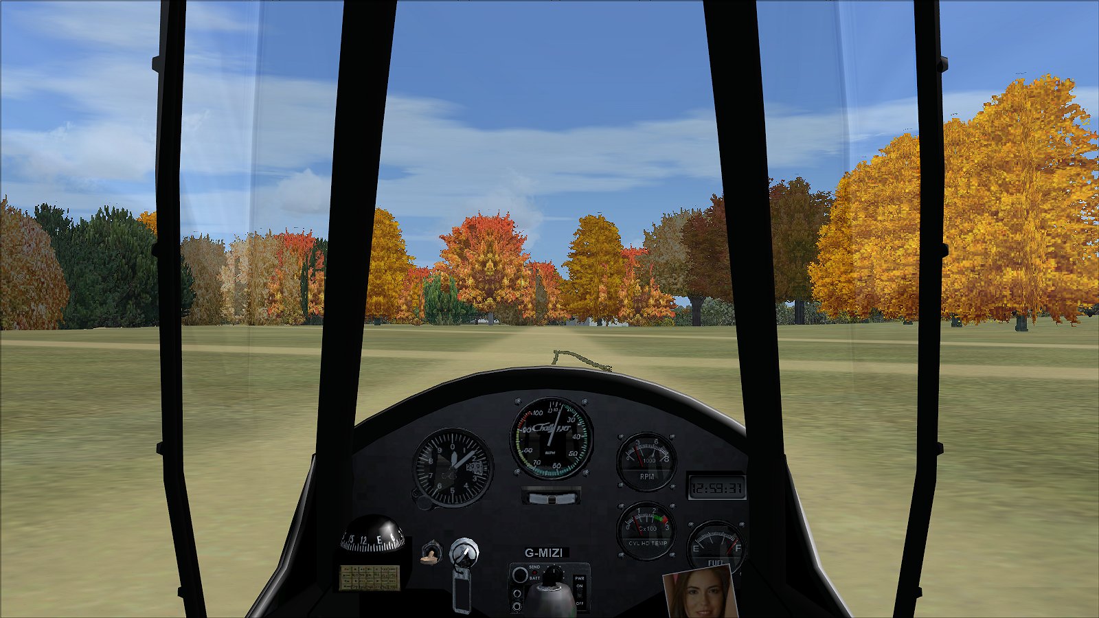
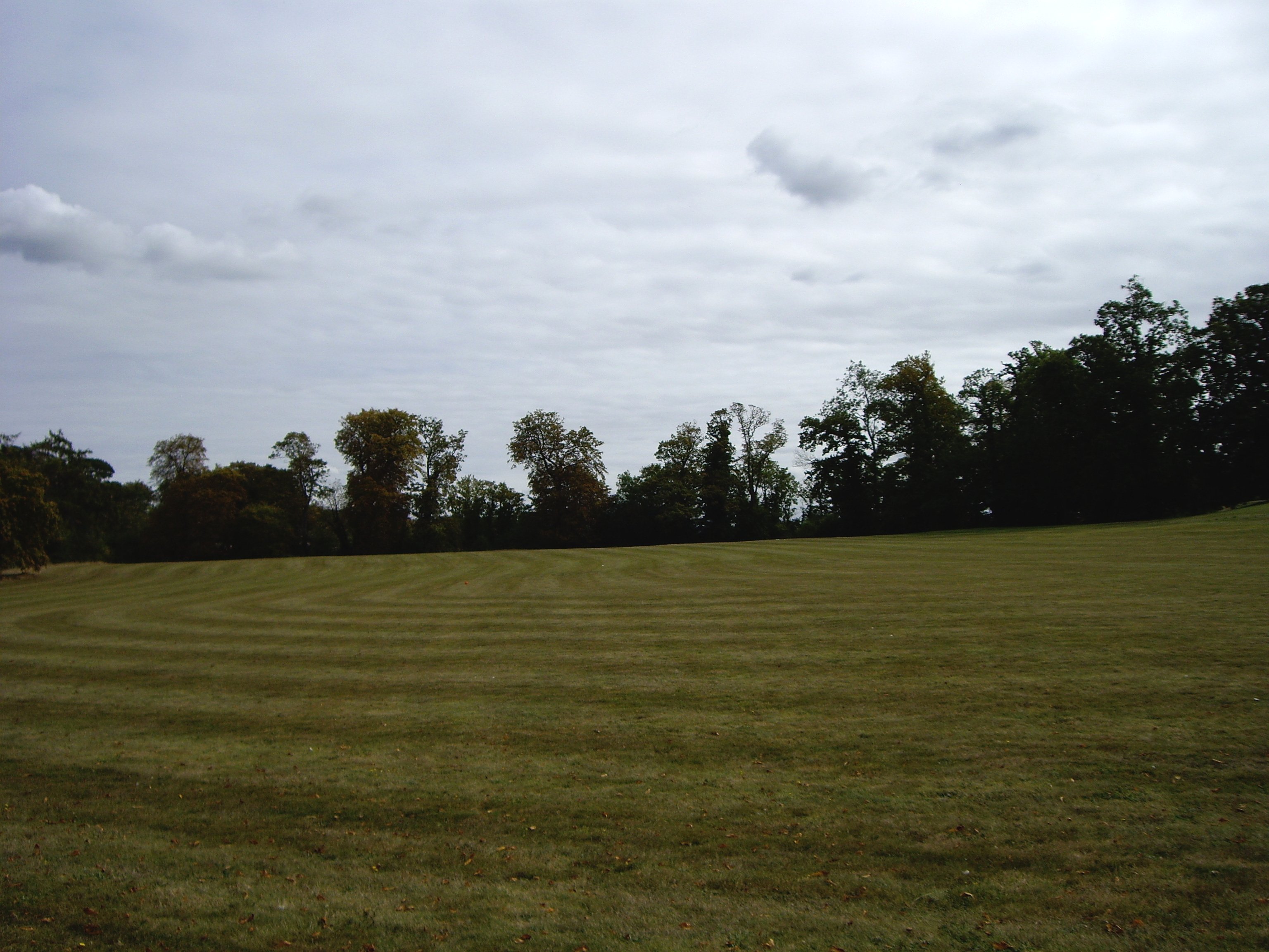
In the last couple of evenings I’ve knocked up a scenery for Microsoft Flight Simulator X (don’t laugh 🙂 ) based on my friend’s property and in which I’ve tried to place trees and bushes as far as possible in their correct places and of about the right heights. Just so you can see how close it is, here are a few comparison pics and I’m sure I won’t need to say which ones are real and which are not 😐

null

null

null

null

null

null

I won’t bother showing the reciprocals and I hope you’ll agree that the scenery is not too far out. The aircraft in the sim, by the way, is a Quad City Challenger that I’ve given flight characteristics to that are very similar to those of an AX3. What I’ve found is that in the sim, it is possible to take off without too many problems. However, landing is much more tricky and speed control on the approach has to be VERY accurate. I haven’t been able to model the up-slope that would help you to slow-down once landed in an easterly direction but stopping does not seem to be a problem in the sim. But what I have found is that whereas the ‘runways’ look totally adequate at ground level, on landing approach they are much foreshortended and from the air they do look very short indeed!

This is something I’ll have to think about. My friend himself said that he thought the space might be a bit small and mentioned that he has another area of land nearby that could possibly be more suitable. I think I may need to find out more 😉

Rather frustrating week-end

I trimmed the bottom of the screen back to the rear edge of the pod on the passenger side so both sides matched and got the passenger door on without too many problems. I then did what I should have done before I started heaving and yanking the other door, which was drill through the pod and screen and insert a small pop rivet with washers both sides to pull the edge of the screen back onto the pod. Then the door cleared it and closed beautifully without coming anywhere near to catching it.

What an idiot I am – if I’d done that originally I wouldn’t have damaged the other door. We certainly learn by our mistakes, don’t we – it’s a pity that some lessons are so painful and costly 😕

I phoned P & M to order a new door tube and Jim said they don’t have them any more. He said the best he could do would be to sell me a metre and a half of 1/2″ tubing which I’d have to bend up myself so I had to agree to that, but I’m not particularly looking forward to the prospect.

I gave the inside of the pod a good old vacuuming out because with all the drilling and trimming it really needed it. Then today I thought I’d knock out my radio interface. Looks like I was rather over-optimistic once again because it took me much longer than I anticipated and at the end of it all, it didn’t work. The intercom side of it worked OK and I could hear the radio through the headset but the PTT (push to talk) button that I made up was as dead as a Dodo. Obviously one of the connections is duff – and I thought I’d made a nice neat job too. I tried the PTT that came with the set up and that didn’t work either and I’m not really surprised because although the system didn’t have one to connect into the radio when I got it, it made sense that it should have done. The PTT lead was there but had been cut back and foolishly I stripped it out as it wasn’t being used when I was getting the system ready to be modified. So now I’ve had to order a length of multi-core cable and a 5 pin DIN plug to make up my own cable with a PTT connection from scratch.

So the week-end started and ended on a frustrating note and I just hope I don’t have too many more like it because time is marching on and the evenings are drawing in now, leaving much less time to get jobs done after the working day.

Drat and double drat!

After my earlier post, I did indeed slip out and get cracking on the padding and doors and my aim was to get the left side done today and the right side tomorrow.

I got everything off that I needed to pretty quickly and the first thing I found was that it wouldn’t be possible to slide the new rubber tubing onto the fuselage tubes after all. The internal diameter of the tubing is just too close to the tube diameter. You’d never be able to slide a whole metre length on, but it wasn’t hard slitting one side down with a large pair of sharp scissors and it looked OK when fitted.

Anyway, I got it cable-tied into place and then lined the door up. The left hand door has always been low at the front and high at the rear so I decided to be bold and as I am making up complete new hinge plates anyway, trim the lower edge of the screen back as it is quite a bit proud of the back edge of the pod. Then I drilled the new hinge plates and fitted the door. Result – pretty good. It was now much more level than before and the new hinge looked very neat and strong. Only one problem – as before, the bottom of the door tended to catch the edge of the screen when you opened and closed it.

So I pulled and pushed to get the amount of movement I needed for it to clear, and it just about did so. So, clever me, I decided to give the bottom a last yank over my knee – and snapped it at a rivet hole 😕

Suffering cats, the job’s done and now I’ve knackered the door tube. Now I’ll have to order a replacement from P & M and I hope to goodness it doesn’t come pre-drilled for pop rivets because if it does, you can bet the holes won’t line up with the ones drilled through the new door plastic for the old tube. So I end up solving one problem and creating another. I’m cheesed off to say the least 😯

And do you know what? The new padding didn’t make that much difference to the space in the cabin anyway…

Just waiting…

for the few more odd bits I’ve ordered for my radio interface to arrive (I can’t hear the doorbell from the garage as I’ve found several times to my cost) and then, as I’ve now also got the aluminium for the hinge plates, I’m going to do some work on the tube padding and doors. In fact the weather is SOooooo good for flying today that I thought of giving Rosie a ring and doing an hour or so in MZEL but although I’d love to, I think the time would be better spent working on MYRO. Mind you, I need to get down to the strip again at some time just to check that MYRO’s wings are still OK – I’m sure they are, though.

I’ve been doing a bit more thinking about MYRO’s pod graphic and I’ve come up with what I hope will be the final version. I’ve simplified the background by bringing the two sections together which removes the gap that rather confused the issue and slightly enhanced the wording. It’s shown below as a mock-up – see what you think.

null

I think that’ll have to be it – I’m now totally out of inspiration 😕

Oh… there’s the doorbell now 😀

Lovely stuff!

The three lengths of foam tube that I ordered from the company near Maidstone arrived today. It is excellent in appearance, of very high quality with lovely thin walls. It’ll make for a really nice job. I wish I’d known about it before but the trouble is, unless you’ve done something like this previously, you don’t know what pitfalls you might fall into. It looks so nice that I’m thinking that rather than slitting it along its length and wrapping it around the tubes, like I did with the pipe insulation, I might release the tops of the two fuselage tubes (again!) and slide it on. It’ll take longer but it’ll look so much better. Now all I need is the aluminium sheet to make the new hinge brackets out of which is on its way (yes, you’ve guessed it, off Ebay) and I can go ahead with the job of removing and replacing the thick padding. Be nice if I could find the odd hour during this week so I can have it done before the week-end 😉

Graphic language…

… is what I feel like using!

As you can’t get hold of the official AX3 pod transfer any more, I’ve been playing around with designs for a vinyl graphic to stick on each side of the pod. I’ve created (and rejected) dozens over the past few weeks and I’m now rapidly becoming paranoid because whenever I design one I like, when I next look at it, I don’t 😕

I asked the guys on the BMAA forum what they thought but haven’t had any useful pointers, really, so as of now I’m stuck with my ‘preferred’ choice. Before I go any further, I knocked out a couple of examples on my laser printer, cut them out and stuck them on one side. The smaller one looked silly and the one I’m currently running with is shown below.

null

Amazingly, the graphic shown is a metre long! I think that’s a little bit too big, but the general conclusion I’ve come to is that you won’t be able to really tell what it will look like until the engine and everything else is fitted and possibly even the wings too. By way of comparison, here’s how my original photo mock-up looked.

null

Not too different, is it? But the lettering needs to be smaller, I think, and the body of the background made ‘fatter’ vertically, to look more like the original.

The Vertex car charger arrived today so I’ll be able to start work on the radio/intercom system now. I also ordered the three lengths of thinner foam tubing. I couldn’t arrange to see them first because the supplier said that my order was below their minimum value anyway but they’d process it if I just put it through on the Internet. Alright for some eh? Minimum order values in these straitened times – what luxury 😀

Chill-out kind of a day

I thought I might as well use today to clear up all those nitty-gritty little jobs that you always leave and say that you’ll do later but often never get round to. First I nipped down to B & Q to buy some aluminium for my new hinge plates and a pack of stick-on draught excluder to go along the bottom edge of the cabin top plastic where the doors come into contact with it. B & Q’s was rubbish and I got exactly what I was looking for from Wickes. Foolishly I didn’t measure the dimensions of the hinge plates and the small sheet of aluminium I bought turned out to be too narrow so I’ll have to look for another source for that one.

I’m glad to say, though, that the sum total of what I achieved today was very satisfying. I replaced the cable-ties holding the fuel cock to improve the appearance, cable-tied in the radio aerial lead to make it nice and tidy and fitted a specially cut piece of 1mm polycarbonate to cover a 6″ gap that exists in the middle between the seats between the back of the pod and the fuselage rear cover. It’s something I had in mind to do because I lost a retractable chinagraph pencil out of the bottom of MYRO when I was flying months ago and my solution will help to avoid that kind of thing happening again.

I also fitted the nose steering links between the rudder pedals and the front forks. Rosie mentioned ages ago that there are two types and that once when she ordered some replacements the ones that arrived were too long. I was disappointed to find that the ones off MYME suffered from the same problem and I guess that must mean that MYME’s pedal assembly must have been positioned slightly further back than MYRO’s. Maybe Cyclone received a complaint from long-legged pilots that they couldn’t get in! Anyway, there’s always a silver lining… because one of the old ones had a little bit of surface rust on it, I cleaned it up and gave both a coat of white Hammerite. Very nice – a big improvement on the originals 🙂

But the last thing I did that I was very pleased about was I repaired the little nip on the pod that was caused by the front forks when I first refitted the pod all those weeks ago. I always knew that I should and that if I didn’t and began flying MYRO, the damage, small though it was, would get dirty and then it would be too late.

Well, now I need feel guilty no longer. It’s done… chill man 😉

All very frustrating

I took another look today and had a sit inside and I think if I don’t replace the thick padding, I’ll probably regret it later on. It’s very frustrating because I’d hoped to get a lot done this week-end (and the weather is going to be good too) but in the whole scheme of things, what’s another week, really?

I did a quick search on the Web and found a company not far from me, near Maidstone, who sell various foam rubber components, including tubing. From their price list I’d need tube with internal diameter 27mm and 5mm wall thickness, which is less than half the thickness of the padding I’m currently using. It comes in black only in 1m lengths at £10 a time (not cheap!) and I’ll need 3 lengths so I think that’s the way to go. I might even be able to pop down there on Monday if I can find the time, to pick the stuff up so then I won’t feel quite so bad as the time lost will be fairly minimal.

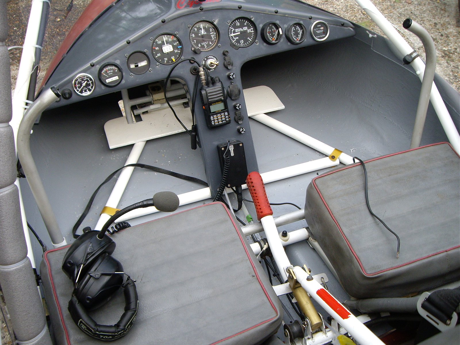
As I couldn’t do much else, and quite frankly I didn’t feel like doing much to be honest, I decided I’d take a look at fitting my radio transceiver and interface. The transceiver is a brand new Vertex VXA-220 that I bought off Ebay from Hong Kong. It’s a superb piece of kit and will be much better than a crumby old semi-obsolete Icom. Been there, done that with Rosie’s 😕

The interface is a used Comunica which I bought with two headsets also off Ebay a couple of weeks ago. I know how to adapt it for my set up but I can’t do the job because a car lead for the Vertex that I bought off Ebay over a week ago, again from Hong Kong, still hasn’t arrived. I only need the angled plug off it (the whole lead only cost £4.50 including postage) but without it it hasn’t been worth starting the job. See what I mean about frustrating?

Anyway, the other day I cut the wide Velcro strips (yes, also off Ebay 🙂 ) that I’ll be using to mount the kit on the panel so I thought I’d see where the best positions for it are. Here’s what I’ve come up with so far.

null

I need to have the transceiver high enough to be able to reach it and see the screen (one of the constant problems with Rosie’s old Icom) but leave enough space so as not to interfere with switches and controls and also not have wire and cable hanging around where someone (me or my passenger) could damage it or inadvertently pull out a plug. More tricky than you might think. Oh yes, and I must also leave enough room for the main placard on the panel as well 😉

Mind the doors!

Things were quiet late this afternoon so I thought I’d nip out and see if I could get the other door on. Having worked out a technique when I did the first door, the second one went on pretty quickly. It was again ‘off’ by the same amount as the first door compared to the original and the main conclusion I have come to is that it’s due to my having used thicker padding (good quality central heating lagging) on the cabin tubes that the doors are mounted on. In fact I’m sure that’s the reason. I don’t think it will cause a problem and I’m hoping that the thicker padding will last longer and not become as tatty as the original stuff did.

One interesting thing I found is that because I’d taped the first door closed, when I removed the tape it had developed a ‘memory’ and returned to the closed position much better and more easily after being opened. After I’d done the second door, I did the same thing and I hope that it will do the same as the other one. Here are a few pics showing the finished results.

null

null

null

Now it really is beginning to look like a proper microlight 😉

I’ll leave this latest door overnight and then see what adjustments are needed. At the moment the bottom isn’t tucking in every time but I’ll see how it is in the morning. The other thing I’ve found is that because the doors swing completely forward when opened, the door plastics come into contact with the nuts on the four little bolts on each side that secure the hinges to the hinge plates, which explains the damage I saw on the old doors. What’s needed is a small, light metal plate to be stuck on the outside of each door plastic so it touches the nuts rather than the plastic, so I’ll look into that tomorrow as well.

I’m just glad that this particular job is finished. However, I’m now facing a dilemma. I’ve only sat in MYRO a couple of times since it all started coming together again and I had the feeling of being a bit cramped that I did not remember from before. I especially found it a bit tight around my left arm that you have to use to operate the throttle and now I’ve realised why. It’s that thick padding – because of it I can now see that I’ve lost something like 1/2″ of cabin width each side compared to with the original thinner material.

The problem is, I’m now always going to know that – and will it affect my enjoyment of MYRO? I don’t know, but I suspect it will 😕

Easy, you say, take out the thick padding and replace it with thin stuff. That will certainly solve some of the problems but it will create others, in particular the cable-tie holes for the hinge plates that have now been drilled through the screen will all be in the wrong places and, what’s more, the wrongly positioned holes will all be visible.

So there’s my dilemma. I know something’s not right, but if I correct it I’ll create other problems. The only way to do a ‘proper’ job is to discard this screen and make another one. That would make things perfect again and wouldn’t cost a lot in financial terms – only £40 or so for the plastic – but it would be costly in terms of time. My guess is that it could put things back by about a fortnight. Plus there’s the disruption – it would mean unbolting the lower fuel pump and pump drain and removing all the bolts holding in the panel, amongst others.

However, I think that after mulling this over for just a few minutes there’s a solution that will avoid all of that. That’s to make up new hinge plates with the cable-tie holes in slightly different positions and to also add cover plates on the outside. The cable-ties will also go through these and they will cover up the incorrect old holes in the screen. I’m sure that will do it and I think the final result will also be perfectly acceptable visually. I think I’m already beginning to breathe a small sigh of relief 😐

Could have been much worse…

For most of the summer we had non-stop strong westerly winds down here in the South-East and for the last week or so we’ve had non-stop strong easterlies. The difference is that because the easterlies come to us from over the North Sea they tend to be cold and also accompanied by low level cloud, both of which we’ve had. So the weather has not been very nice at all for several days.

Even so, I’ve tried to do what work I could on MYRO despite the unfavourable conditions. Last night I decided I’d attach the new cabin top plastic in readiness for fitting the doors so I began by doubling up on the padding on the upper parts of the cabin tubes to which the rear of the screen is attached, as had been done originally with MYRO. I especially thought that the extra thickness on the very top sections would be advantageous in helping to encourage the top edge of the screen to sit up, allowing the top edge of the door to tuck under, so that’s how I did it.

After a fair bit of fiddling around with cable-ties the job was completed so before I cleared up and headed back indoors I thought I’d see how a door lined up. I offered up the left-hand door and was stunned to find that it seemed to be a mile out! This was not only unexpected but was also the nightmare I feared most after all the work cutting and assembling the new plastics. After the inital shock had worn off I looked a bit more closely and came to the general conclusion that although the double padding was a good idea, maybe the amount I’d fitted was a bit over the top. So I decided that next time I’d take the double thickness off, fit the doors, and then add the double thickness afterwards rather than before.

So that’s what I did this evening. Off came a whole bunch of cable-ties that I’d only stuck on last night – I find that I keep doing this and the number of cable-ties I’ve wasted must now run into dozens – and off came the extra tube padding. Then I refitted the ties securing the front of the cabin top plastic and tried offering up the left-hand door again. This time it all looked much better – a huge improvement actually. Even so, despite using the old parts as patterns, there were one or two small differences, but nothing that was unacceptable or, more importantly, unsafe.

So I held the door in place with several lengths of wide masking tape, took a deep breath and drilled the screen for the hinge plate. Then I fitted it and attached the door. I could hardly bring myself to try closing it for fear that it wouldn’t, and indeed it didn’t. But nothing too much to worry about. First, my idea of extending the top edge of the door was a good one and looks effective, but I’d taken the extension a bit too far down so it was digging into the tube padding before the door was fully closed. A few minutes work with Stanley knife and file solved that one. Then I found that due to a slight misalignment, the bottom edge of the door was not always tucking in behind the edge of the screen and the pod, so I jiggled things a bit, carefully applied a bit of pressure to the door tube and that seemed to solve that one. If not, I can do a little bit more of the same.

To cut the story short, in the end the door didn’t look at all bad and seemed to open and close at it should, so to finish I cut down the extra tube padding that I’d removed earlier and refitted it. And that’s where I left it. I’m going to add a couple more cable-ties to the rear edge of the screen on the cabin tube to tighten it up and bring it more into the desired shape which will also have the added benefit of encouraging the bottom of the door to tuck in as it should do. So am I relieved? You bet! This was a job that I was a bit worried about as the door fit is absolutely crucial to safety. Was it the nightmare that I expected it to be? No, not really, but it was definitely a bit tricky and needed quite a bit of working out beforehand. In the end I think it could have been much, much worse – but I mustn’t speak too soon as I’ve still got another door to do 😕

Oh yes, a bit of good news to finish on. Having tracked down the provenance of my Arplast prop and liaised with LTS (the UK Arplast agent) and the BMAA, I received an email from Rob in the BMAA Tech Office today saying that the prop has now been approved and I can go ahead and fit it. So just the small matters now of the paperwork and £40 Mod Fee…

Doors on? Dream on!

It’s been another very long, tiring week-end. I was going to leave replacing some old, rusty nuts and bolts until after I’d done the doors but I did it instead as the first job on Saturday and as things turned out, I’m glad I did.

There are four bolts, two each on either side of the main tube in the top of the cabin that secure the cockpit side tubes to a bracket on the main tube. These were rusty and when I first started on MYRO, I ordered some replacements from P & M Aviation. However, when I came to fit them a few days ago, although the replacements were as specified in the AX3 Parts List, they were too long.

When I ordered some more items last week, P & M kindly offered to replace the long ones free of charge, which is typical of how I’ve found them throughout the whole project – very helpful and always offering excellent service. So I put the new ones on first.

The other thing I found was that when I replaced the nuts on them several weeks ago now, the thread on one of the two large bolts that pass horizontally through the main tube and secure the engine mounting brackets had stripped. When I ordered a replacement bolt, again several weeks ago, I could not remember which one it was so I ordered two and decided to replace both of them.

Lucky I did, because when I removed the second one, its thread was also very badly worn and most likely would not have lasted for very much longer.

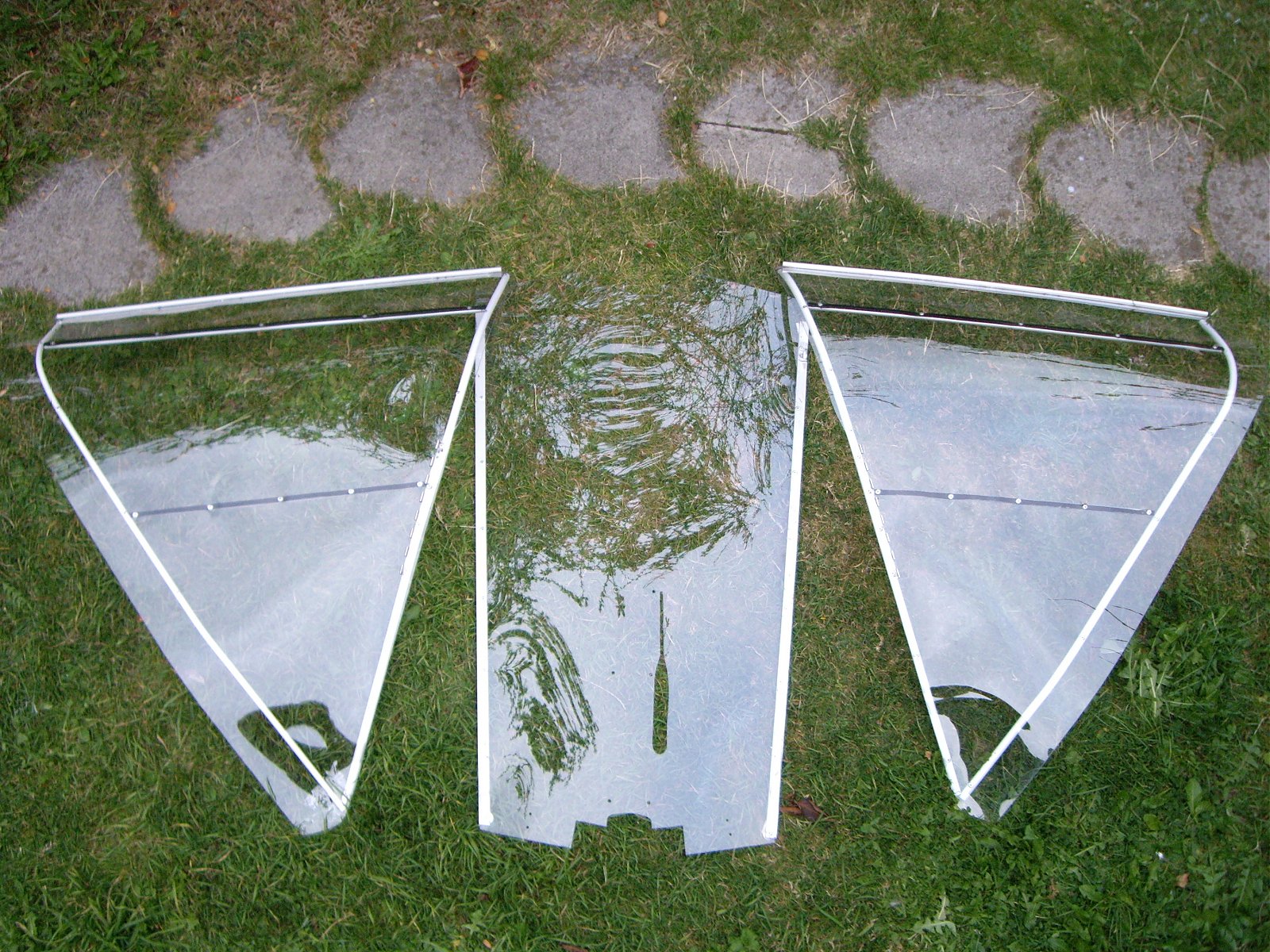
And so I came onto the doors – doors and cabin top plastic actually. I took a few pics of the doors as references as I do so I know how things go back together when I’ve stripped them but mostly they were not suitable for inclusion here. Suffice to say that the left hand side was in considerably worse condition than the right, with lots of little splits, holes in the wrong places and digs out of its edges. The following pic shows the right hand door, the better of the two.

null

The multiple drillings in the hinge I could do little about, but I was able to do quite a bit to improve the overall appearance. The main thing was to spray the front and rear door frame tubes, which were a mucky gold, white which will help in my aim of making the cabin as bright as possible.

I also found some right bloomers, which I was able to correct. For example, one of the cross tubes had been put on upside-down and someone had drilled a completely new set of rivet holes. Why would anyone do such a thing 😯

I made up a new left-hand door yesterday and today I did the right-hand and the cabin top plastic. I have to say that I was surprised how long it took – I expected to have the doors made and fitted in a week-end. Dream on! I ran out of time today long before I’d had any chance of even starting to fit them.

The following pic shows the final results.

null

I’m pleased with the way they’ve turned out – I didn’t make any mistakes and in fact I added an extra small modification. There have been one or two instances, one quite recently, of doors blowing off in flight. I think the only way this can happen is if the upper front door edge is not tucked under the windscreen when the door is closed, allowing the airflow to get under it. I checked and MYRO’s doors always fitted quite nicely but just in case, I’ve extended the door front edge to give a bit more of an overlap. You can just see that in the above pic, where I’ve made the upper front edge of each door extend a half inch or so beyond the front tube between the hinge and the top of the door.

I hope this small modification works, but mainly I just hope now that the new doors will fit!

Sweating it out with fingers crossed

A friend of mine owns a property which is surrounded by grassland a sizeable chunk of which is pretty flat. I asked him a while ago if I might be allowed to keep MYRO there and he said he couldn’t see any reason why not. I reminded him of that the other day and he suggested that I should go and have a look as I hadn’t seen the property up to then.

When I arrived I was literally gob-smacked. The property itself is beautiful but what’s more relevant to me is that it sits next to a small area of microlighting heaven. The land is fairly elevated so it’s pretty well drained for starters which is helped even more by the ground being quite sandy. Also the area in question is firm, flat and evenly grassed with only a modest east-west downslope and also nicely shaped so you could have a choice of directions in which to land and take off.

The shortest ‘runway’ would be 06/24, shown below, at 175 yards. At one end there is a wide gap in trees on the perimeter and at the other a group of low trees situated some way from the end of the ‘runway track’.

null

null

The next would be 11/29 at 210 yards, shown below, with medium-size trees at one end and low trees at the other.

null

null

And finally there’s what would be 08/26 at 250 yards, again with medium-size trees at one end and low trees at the other.

null

null

There are no nearby neighbouring properties that would be overflown on any of the above ‘runway centrelines’ which is, of course, a very valuable bonus and there’s even a lovely little sheltered spot between some high trees where MYRO could be left safely tied-down under covers.

At the moment my friend is still thinking about it so I’m having to sweat it out with my fingers crossed. I really hope that from my point of view he comes to the ‘right’ decision because as well as solving a key problem for me, it would also give me a superb venue to fly from, as it’s situated quite nicely almost in the centre of Kent.

I’ll let you know how it turns out.

Bit of a lull

Was talking to P & M yesterday and I’m now expecting the rivets and bolts for the doors to arrive at any time. I’ve spent the last couple of days mulling things over and thinking about the next stages of the project and I’ve taken the opportunity to take a look at something that’s been slightly troubling me.

On the face of it, it appears to be a relatively minor thing – when the engine is fitted, will MYRO still fit in my garage? The total height of the garage interior is, of course, much greater than MYRO with its engine fitted (different story with the tail fin on though) but getting it in is the problem. I’ve got an up-and-over garage door which doesn’t rise to anywhere near the top of the door opening and there’s no way of making it go any higher. My initial feeling was that by eye, MYRO wouldn’t be able to get through the open door once its engine was on.

Now if this is right, it presents me with a problem. If MYRO can’t get into the garage it would have to stay outside and that’s not something I want to happen for any length of time. So I’d have to arrange to fit the engine more or less the day before I took MYRO to wherever it goes to have its wings fitted. Obviously, that would not be very convenient. I’d like to get everything done, fitted, connected and set up in plenty of time before getting ready to fit the wings – and I mean potentially weeks before because quite honestly, as yet I don’t know where the wing fitting, weighing, inspecting, test flying and permitting will be happening. Although I may be given permission, it’s possible that I will not be allowed to do all that at the place where the wings are currently hanging on the hangar wall and I’ll have to find somewhere else, so it will take a lot of pressure off if I can go ahead and finish absolutely everything that I can do here in my garage without having to also plan for such intricate timing and logistics.

However, today I made some quick measurements and if I’m correct, there will still be an inch or so of clearance. I hope that my numbers are right, as that will remove a bit of a worry but anyway, we’ll see when I can measure up again a bit more accurately 😉

New video

I put a new video in the gallery yesterday evening. It’s just over 10 minutes long and it’s a kind of work in progress, showing how I got started in the MYRO project and where I’m up to. You can see it by going to the video page and selecting the video called ‘MYRO – The Next Chapter’ or by clicking HERE.

It covers everything right from the beginning and as I go I’ll be adding to it until I’ve got a video covering everything from beginning to end. I’ve never been very good at taking photographs and movies as records of events, except for things like holidays when I was younger, so this will be a bit of a first for me. I’m very happy about that 🙂

Last lap… almost

I knew that once I’d got the pod back on and the new screen fitted, things would happen pretty quickly, but even I’m surprised at just how fast things are moving along. Apart from adjusting the throttle cable when the engine and carbs are on, the cabin really is finished. That’s if you don’t include cleaning the seats, oh, and swapping out some rusty nuts ands bolts up-top which I forgot to do previously. That’ll only take twenty minutes or so tomorrow so it’s no big deal.

The first thing I did today was connect the outer drain tube to the lower fuel pump, as shown below.

null

Now I haven’t the faintest idea how this is supposed to work, but all I do know is that when I got MYRO, it had a build up of oily residue below the pump inside the pod and when I last looked, MZEL is going the same way. I thought the pump was a totally sealed unit but the man at P & M said something about there being a minute hole for any muck from the crankcase to drain out of. I don’t know what he meant but when I put the pump in, I put a smear of clear silicone on the surface of the pump that goes against the pod side in an attempt to prevent the oily muck from coming inside. Then I added the flimsy little rubber ‘terminator’ on the outside (which quite honestly I don’t think is the correct original part – it’s more like just a rubber battery terminal cover) and tried to seal round that with clear silicone too. Only time will tell if what I’ve done will work, but it’s a bad business when oily muck comes inside where you might have stowed a map, an article of clothing, something like that.

Then I turned my attention to the main wiring. Although I had cable-tied it all into place, up to now I’d only labelled the wires up and hadn’t actually made the connections. Because the wiring is a bit of a mixture, being mainly from MYME but with a few modifications that I’d thrown in, it wasn’t just a matter of connecting it all up by plugging in a few bullet connectors. Some wires had been damaged or, frankly, just connected previously in a very haphazard way and some were a bit short even. Although there was already an in-line fuse in the main 12V supply, I had to add one into the ‘black’ connection from the rectifier to the battery, which had been omitted. I therefore decided some time ago to use two fuseholders that were of the same design and could be clipped together, which meant modifying what was already there.

There is no need for bodged, insulation taped-wrapped connections nowadays. Heat shrink sleeving makes joins unobtrusive and professional looking and if you use insulated connectors (bullets and spades) properly crimped using a tool that only costs a fiver or so, you get a nice looking job that you can not only be proud of but that will also work reliably in the future. Here’s a pic showing the connections around the rectifier and the two new fuseholders.

null

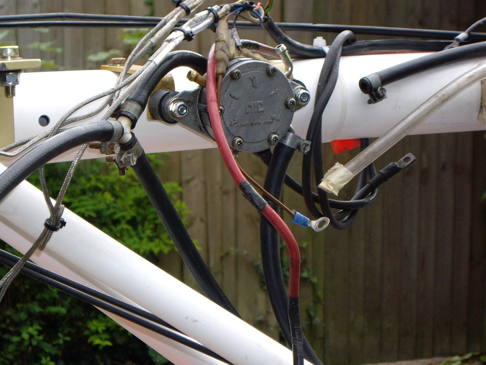
There are still a couple of odd earth wires floating around there but I’ll leave them for the time being until the engine’s on and I can see exactly what earth(s) I’ll need. The one-into-two black cable, by the way, is for the carburettor chokes. The next shot is of the upper fuel pump and it shows how all the connections are now just waiting for the engine to be dropped on.

null

The heavy red cable will connect to the starter motor and the heavy black cable that is just hung on the tube for now I intend to connect back from the engine to the battery as the main earth. The bunch of connections above the fuel pump are the CHT and EGT sensors among others, which needed quite a bit of work a week or so ago when I was sorting out the wiring loom. I think all that work was well worth it now I can see it all falling into place.

Now back down to the cabin. As you can see below, I’m very pleased with how the electric fuel pump has slotted in nicely against the pod wall. I feel very fortunate as Rosie wasn’t quite so lucky with MZEL’s which had to be positioned slightly differently and hasn’t gone in quite as neatly.

null

I put the black insulation tape on the tube while I was experimenting where to secure the throttle cable to and they will eventually be removed. The electric fuel pump connects to the fuel cock and the following pic shows how that is secured to the side tube.

null

Originally I only used two cable ties but I added two more which also pass through the screen slot and hold the vacuum pipe to the side tube on the outside. They also stopped the cock from being able to rotate slightly on the tube but at the moment I’m not happy with the appearance and I’ll have to cut all four off and re-do them. Notice how I’ve run the wires to the electric fuel pump up behind the bottom edge of the screen. I’m very proud of that and I also think it’s a good idea because it means that no wires are accessible in the cabin where they might be caught in any way or cut.

I am very pleased indeed with how the appearance of MYRO’s cabin has been improved out of all recognition compared to the way it was when I got it. With the wings off, the cabin appears lighter than it will do eventually but even so, I think it has taken years off MYRO.

null

I can hardly believe that I’m almost ready to drop the engine on – in fact it would only take a couple of hours or so to get it on and connected up. However, I’ve still got the door plastics to do when the rivets and new bolts arrive and the tailplane has got to go back on as well, so there’s still a bit to do. But even if I can’t quite see the winning post just yet, at least the last lap is now in sight 🙂

Loose ends tidied up

Took the opportunity to finish off the week-end’s left-overs and do a bit more this afternoon. I couldn’t get a 1″ tank cutter to drill the hole through the new screen for the lower fuel pump so I bought a pack of three sharp wood bits instead. I’d used a 13mm one of those to make holes in the panel so I knew a 25mm one would do the job fine, which it did. So I got the fuel pump permanently bolted in. I also re-fitted all the cable ties that I’d had to remove on the wiring up to the main tube and I experimented with fitting some pipe insulation as draught excluder in the front tube screen slot but I don’t like the look of it so I’ll try a different approach. As I had MYRO’s original length of rubber tubing that connects to the engine crankcase and runs between the vacuum connections of the upper and lower fuel pumps I connected that as well.

I then decided I’d finish off the cabin by connecting the lower fuel pump to the fuel cock and running the tubing from that to the upper fuel pump. I had almost a complete system of fuel tubing that came from MYME so I thought I’d have a look at that and if it was still in good condition, fit it. It was lucky that I did because I found it was rotten and cracked in lots of places. The tubing is the clear plastic type with braiding and there have been several postings on the BMAA forums warning about those exact problems with it, so I’m glad that I had been fore-warned. Luckily I’d purchased a couple of metres of new 1/4″ rubber tubing so I was able to fit that instead.

I then ran the fuel tubing from the fuel cock out through the screen side tube slot together with the throttle cables and by the end of the afternoon MYRO was really beginning to look the business with the fuel line, vacuum tube and throttle cables neatly cable-tied up the length of the diagonal side tube. All I need to do now is make the two connections to the electric fuel pump and apart from finally adjusting the throttle cable when the carbs are on, the cabin will be finished.

I’m almost ready to fit the engine – I doubt I’ll be ready this week-end but at the pace things are moving, who knows 😉

Oh yes, one last thing. I got hold of a couple of used Comunica headsets and a Comunica powered interface off Ebay yesterday. They weren’t too expensive so I won’t mind too much if things don’t work when I start hacking plugs off and making up new connections to suit my Vertex radio. Paul Lintott showed how to do it on the BMAA forum and it was one of his postings actually that originally persuaded me to go for the Vertex rather than an old Icom. So apart from a new battery, that really is everything I’m going to need for a fully flyable aircraft 😀

Screen at last

Today was the single hardest day of the job so far and as I type this I’m feeling pretty whacked. Before I did anything I measured and re-measured the positions of the tube cut outs, especially the side tubes, and I then realised that even though I’d ‘adjusted’ them, the markings I’d made based on the old screen were not symetrically positioned, in fact nowhere near it. Clearly they ought to be, so I looked closely again at the old screen still in position on the pod, made a note of the exact adjustments that were necessary and re-marked them symetrically this time.

Eventually I had to take courage and start cutting and as it happens, the results in the end didn’t turn out too badly as the following pics show.

null

null

Based on measurements, I made the nose tube cut out wider than I instinctively wanted to and my instinct proved to be right on this occasion, although it’s really only a matter of degree. I’m very pleased with the side tube cut outs which were not at all pretty originally. Now they are a nice tight fit without actually touching the tubes and I doubt I’ll need to put any ‘filler’ around them to take up the gaps. The left one I cut slightly longer than the right because there has to be a gap for the fuel tube to pass through.

null

Unfortunately I had to cut most of the cable ties that I had put in place yesterday holding the wiring to the front tube and I also had to drop the panel down to jiggle the screen into place. Drilling out the holes to match those in the pod and panel was not difficult once I’d got everything exactly lined up, but fitting the nuts to to the plastic bolts that I used to secure the whole thing was very tricky and very tiring as I had to lie on my back inside the incredibly cramped cabin and grip the nuts while my son screwed the bolts up from outside. That’s what I mean about it being a hard day, as well as the difficulty of the job. It was bad enough getting in, but getting out was a nightmare 😕

The cabin is now beginning to look a treat and I’m very proud of the way it’s come on compared to how it was when I started. It all looks so much cleaner and brighter than it was and it’ll be nice to be flying in that environment.

null

I didn’t get around today to re-securing the wiring with new cable ties so that’s one of the next jobs. I’ve also got to borrow another smaller tank cutter from my stepson to cut a hole through the screen for the lower vacuum fuel pump and after that I’ll be able to run the fuel system up to the engine. I couldn’t do anything about the door plastics this week-end because Bill Brooks was on holiday last week and P & M need to confirm with him exactly what rivets they need to supply for the doors. However, I couldn’t have got round to them even if I’d wanted to because my tank ran out at just about the same moment as time did. So they also go on the list for next time 😉