


Wiring up an engine ‘à la Rotax’ isn’t that difficult once you know what you’re doing so long as you take your time and are careful, as I found out when I installed MYRO’s wiring loom from scratch. And having done it before, it’s easier second time around, of course. Having seen the back of the X-Air’s panel, I already knew that it needed to be sorted out and once I’d examined it more closely laid flat on the bench, I was pretty certain that some rather unconventional things had been done. Sure, it all worked, but that didn’t make it right. Anyway, I needed to confirm my suspicions by checking the wiring in the aircraft with my Robin meter before deciding what to do about it.
And today my suspicions were confirmed. The Rotax approved wiring diagram shows a connection direct from the black lead on the voltage regulator via a 16 amp fuse to the positive battery terminal. This is the main charging lead. On the X-Air, there was an un-fused connection from under the panel via a length of light-weight 2-core lighting cable, to the battery from a switched circuit controlled by the key. It had been charging the battery all right, but there was no way that I was prepared to leave it like that. The main 12V supply to the panel also has to be connected directly to the black voltage regulator lead but Rotax requires there to be a 15 amp fuse in the line. In the X-air, the connection had been made via a panel fuse direct to the key rather than via the master switch. This meant that the starter could be operated via the key switch but without the master switch being turned on, which didn’t seem at all right to me.
The X-Air has separate magneto switches, of course, which I am not a great fan of. MYRO had a rotary key switch – Mag Left, Mag Right, Mags Both, Start – which I much preferred as it’s secure and the aircraft cannot be started and flown without the key. On the other hand, any aircraft with separate magneto switches can in theory be started and flown just by switching on the mags and swinging the prop. And what’s more, although a thief wouldn’t have any electrical instruments (eg rev counter, water temp gauge) he would still have the basic flying instruments – ASI, VSI, Altimeter – which is all he’d need to fly the aircraft. Nevertheless I have decided to keep the separate mag switches which is the conventional arrangement for X-Airs and anyway, I’ve no intention of stripping equipment unnecessarily out of MYRO as who knows what the future might hold in that respect 😉
I have already produced a new panel layout and wiring arrangement for the X-Air and all that remained today before going ahead and making it for real was to confirm my suspicions about the wiring and make the necessary changes to the aircraft wiring in order to bring it into line with the Rotax recommendations. So that was today’s job. There are two panel fuses in the existing X-Air panel and I want to re-use them, but not in their present functions. In fact I’ll need an extra one, because I want one 10 amp fuse in the starter solenoid circuit from the key and one each of something like 2 amps in each of two panel mounted power sockets controlled by the aux switch. The next question was what to do about the 15 and 16 amp fuses needed for the main 12V supply and the battery charging circuit? I was in luck here, because on the horrible big old electrical filter that I’m scrapping from the existing panel there happen to be two in-line fuse holders (how you’d have got to them under the existing panel is another question) and these were suitable for the job so long as the fuses in them are changed for ones of the correct value before putting the system into service. So having worked all this out I was ready to tackle the job.
X-Airs have two multi-connection plug/socket arrangements, one up near the engine and the other under the panel. There is nothing mystical about them as they do no more than make the same connections that are made individually on the AX3, for example. And in fact they wear, get damaged and can be a source of problems, as I know from having worked on Ken and Peter’s X-Air’s wiring. I suspected the worst when I inspected my X-Air’s wiring up near the engine. There was a large lump of insulation tape with wires coming out of each end and when I removed it, what did I find, but more insulation tape, as shown by the following pic.

The connection to one of the mag leads appears not even to have been made, although it’s possible that the two parts were touching and held together by the tape surrounding them. Now experience has taught me never to trust insulation tape, so it all had to come off, and the awful mess that was below is shown in the next picture.
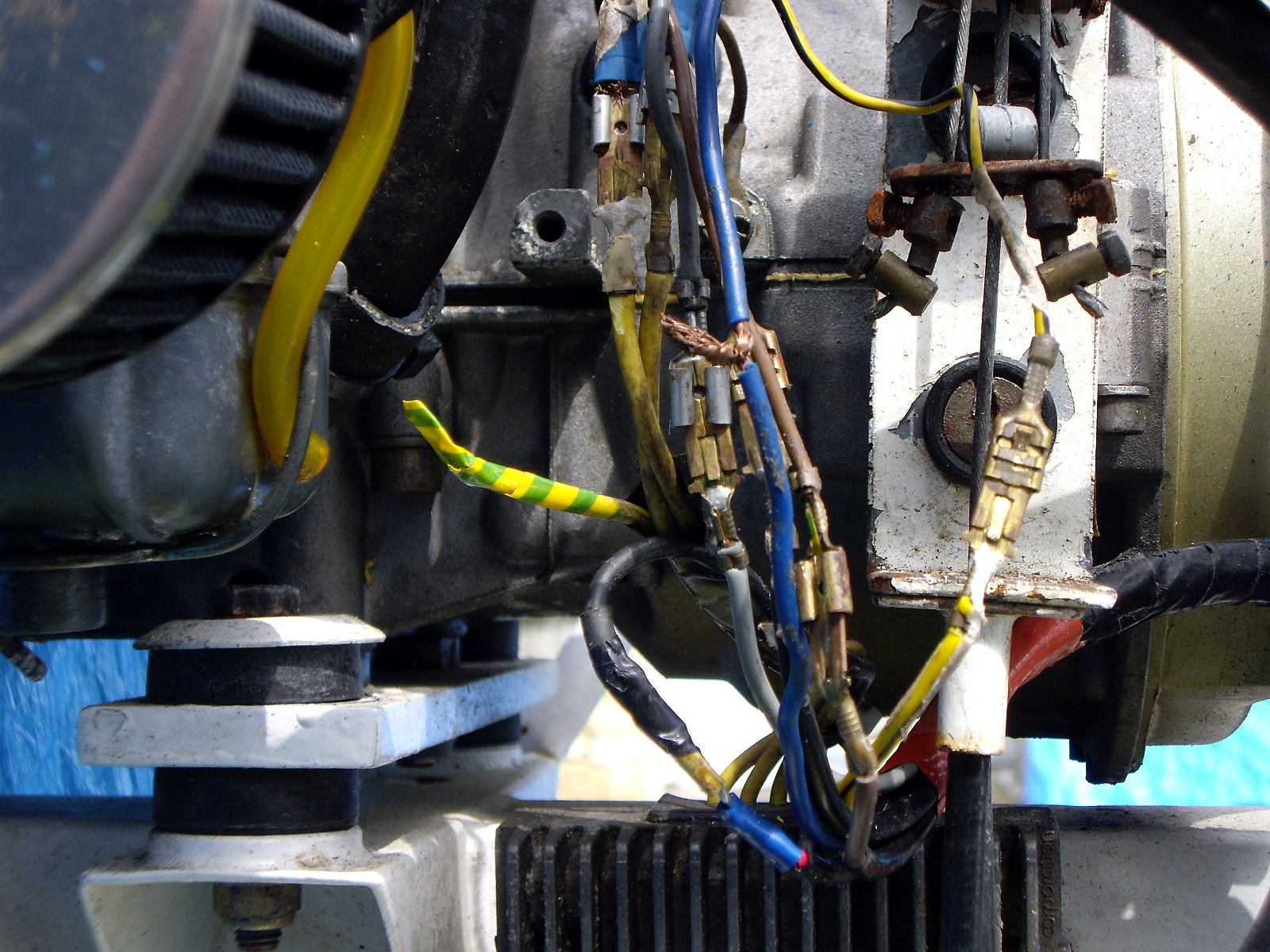
It looked like all the connections that would have been inside the multi-connection plug/socket that I mentioned earlier, if it had been there, and the lead from the water temperature sender didn’t even have a connector – its ends had just been twisted together! It meant that the whole lot would have to be re-done, but I didn’t mind that because I prefer to have connections that I’ve made, that I can trust, rather than someone else’s bodge-up. And in any case, it would also give me the opportunity to take out the nasty light-weight 2-core lighting cable that charged the battery and connected the key to the starter solenoid and put in something proper that reflected what Rotax actually requires.
My friend Wim dropped in for a cup of coffee this morning, which was enjoyable as always, and I got cracking around lunch time. By the time I’d finished and got the X-Air put to bed and covered in readiness for more rain tomorrow, it was nearly 8.00pm. But it was a day well-spent. The final pic below shows what the main part of the wiring looked like in the end.

The fuselage is now ready for the new panel, which I can get on with over the next day or so while it’s raining. That’s OK because I’ll be working on it indoors, so for once although it’ll be raining, no time will be lost. Sometimes even small wins are very gratifying 😉