


I knew that once I’d got the pod back on and the new screen fitted, things would happen pretty quickly, but even I’m surprised at just how fast things are moving along. Apart from adjusting the throttle cable when the engine and carbs are on, the cabin really is finished. That’s if you don’t include cleaning the seats, oh, and swapping out some rusty nuts ands bolts up-top which I forgot to do previously. That’ll only take twenty minutes or so tomorrow so it’s no big deal.
The first thing I did today was connect the outer drain tube to the lower fuel pump, as shown below.
Now I haven’t the faintest idea how this is supposed to work, but all I do know is that when I got MYRO, it had a build up of oily residue below the pump inside the pod and when I last looked, MZEL is going the same way. I thought the pump was a totally sealed unit but the man at P & M said something about there being a minute hole for any muck from the crankcase to drain out of. I don’t know what he meant but when I put the pump in, I put a smear of clear silicone on the surface of the pump that goes against the pod side in an attempt to prevent the oily muck from coming inside. Then I added the flimsy little rubber ‘terminator’ on the outside (which quite honestly I don’t think is the correct original part – it’s more like just a rubber battery terminal cover) and tried to seal round that with clear silicone too. Only time will tell if what I’ve done will work, but it’s a bad business when oily muck comes inside where you might have stowed a map, an article of clothing, something like that.
Then I turned my attention to the main wiring. Although I had cable-tied it all into place, up to now I’d only labelled the wires up and hadn’t actually made the connections. Because the wiring is a bit of a mixture, being mainly from MYME but with a few modifications that I’d thrown in, it wasn’t just a matter of connecting it all up by plugging in a few bullet connectors. Some wires had been damaged or, frankly, just connected previously in a very haphazard way and some were a bit short even. Although there was already an in-line fuse in the main 12V supply, I had to add one into the ‘black’ connection from the rectifier to the battery, which had been omitted. I therefore decided some time ago to use two fuseholders that were of the same design and could be clipped together, which meant modifying what was already there.
There is no need for bodged, insulation taped-wrapped connections nowadays. Heat shrink sleeving makes joins unobtrusive and professional looking and if you use insulated connectors (bullets and spades) properly crimped using a tool that only costs a fiver or so, you get a nice looking job that you can not only be proud of but that will also work reliably in the future. Here’s a pic showing the connections around the rectifier and the two new fuseholders.

There are still a couple of odd earth wires floating around there but I’ll leave them for the time being until the engine’s on and I can see exactly what earth(s) I’ll need. The one-into-two black cable, by the way, is for the carburettor chokes. The next shot is of the upper fuel pump and it shows how all the connections are now just waiting for the engine to be dropped on.
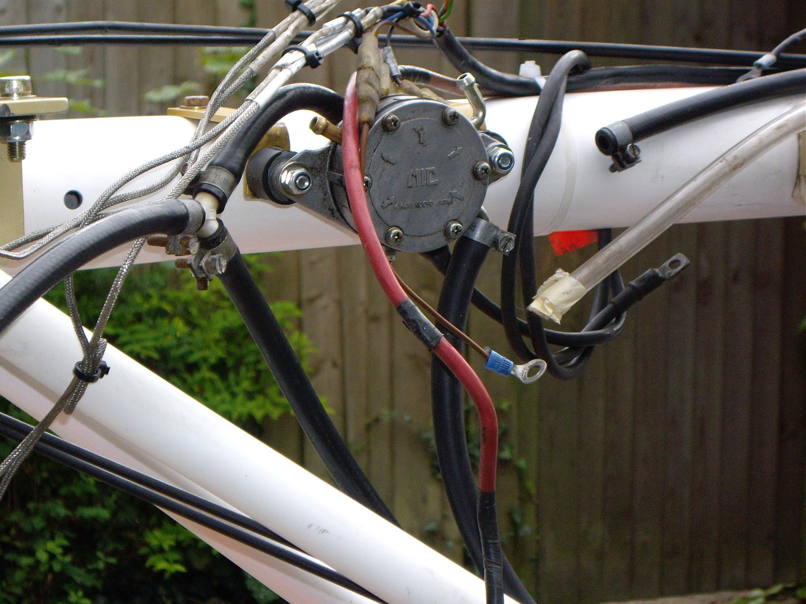
The heavy red cable will connect to the starter motor and the heavy black cable that is just hung on the tube for now I intend to connect back from the engine to the battery as the main earth. The bunch of connections above the fuel pump are the CHT and EGT sensors among others, which needed quite a bit of work a week or so ago when I was sorting out the wiring loom. I think all that work was well worth it now I can see it all falling into place.
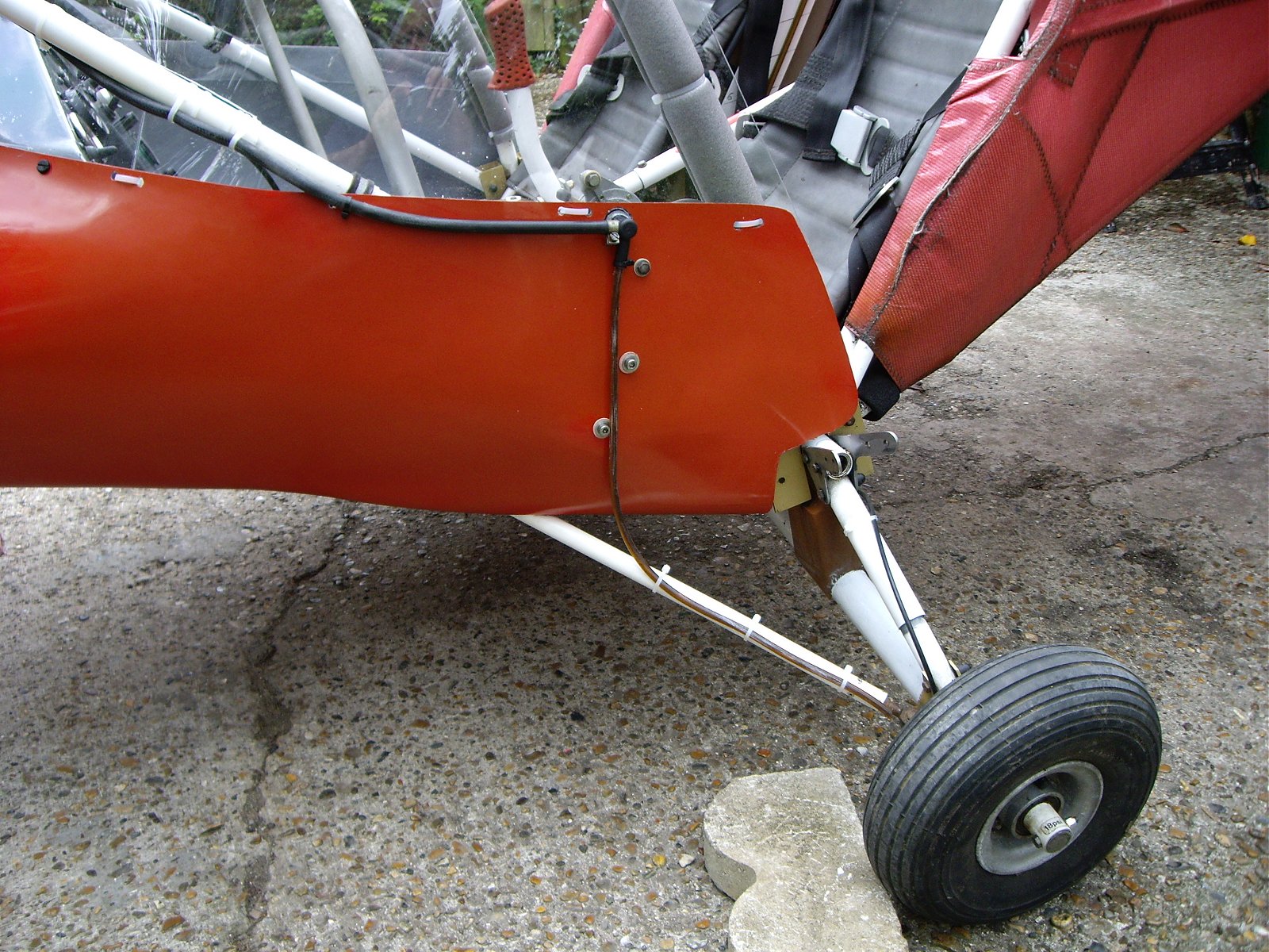
Now back down to the cabin. As you can see below, I’m very pleased with how the electric fuel pump has slotted in nicely against the pod wall. I feel very fortunate as Rosie wasn’t quite so lucky with MZEL’s which had to be positioned slightly differently and hasn’t gone in quite as neatly.

I put the black insulation tape on the tube while I was experimenting where to secure the throttle cable to and they will eventually be removed. The electric fuel pump connects to the fuel cock and the following pic shows how that is secured to the side tube.

Originally I only used two cable ties but I added two more which also pass through the screen slot and hold the vacuum pipe to the side tube on the outside. They also stopped the cock from being able to rotate slightly on the tube but at the moment I’m not happy with the appearance and I’ll have to cut all four off and re-do them. Notice how I’ve run the wires to the electric fuel pump up behind the bottom edge of the screen. I’m very proud of that and I also think it’s a good idea because it means that no wires are accessible in the cabin where they might be caught in any way or cut.
I am very pleased indeed with how the appearance of MYRO’s cabin has been improved out of all recognition compared to the way it was when I got it. With the wings off, the cabin appears lighter than it will do eventually but even so, I think it has taken years off MYRO.

I can hardly believe that I’m almost ready to drop the engine on – in fact it would only take a couple of hours or so to get it on and connected up. However, I’ve still got the door plastics to do when the rivets and new bolts arrive and the tailplane has got to go back on as well, so there’s still a bit to do. But even if I can’t quite see the winning post just yet, at least the last lap is now in sight 🙂